
From astronautix and Wikipedia:
TAV
American manned spaceplane. Developed in the 1980s but halted in favor of the X-30. USAF program of the 1980's that reached the test hardware stage and was leading to a single-stage-to-orbit, rocket-powered, winged manned vehicle.
Halted in favor of the X-30 National Aerospace Plane.
The Air Force's classified Trans-Atmospheric Vehicle development of the 1980's originated with the AMSC (Advanced Manned Spaceflight Capability) program of 1978. This studied the utility of manned spacecraft for military purposes. Trade studies were made of the technical alternates (one or two stages, vertical or winged horizontal takeoff and landing). The technical data generated during the Isinglass program of the 1960's was used as a starting point. The initial findings were positive, and it led to the following technology programs of the 1980's:
•Science Dawn, 1982 - Three in-depth preliminary designs were made by hand picked design teams. The vehicles would have used upgraded shuttle SSME engines. These would operate at 109% and 115% of nominal thrust, be modified for horizontal operation and be equipped with a two-position nozzle for higher specific impulse at high altitudes.
•Science Realm, 1984 - This phase resulted in design of a structural test article.
•Have Region, 1986 - This phase resulted in the actual manufacture and test of structural articles. Three structural concepts, were built. Two were considered partial successes, and one concept was considered completely validated. This used a stainless steel hydrogen tank liner and demonstrated a propellant utilization fraction of 0.88.
This classified work was replaced by the more ambitious air-breathing National Aerospace Plane project in 1986, which itself was finally cancelled due to lack of political support and technology challenges.
Characteristics
Crew Size: 1.
--------------------------------------------------------------------------------
--------------------------------------------------------------------------------
Associated Countries •USA
--------------------------------------------------------------------------------
See also •Low earth orbit
•Manned
•Spaceplane
•US Rocketplanes
****************************************************************
Sortie Vehicle
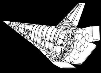
Sortie Vehicle
Cutaway view of Boeing 747-launched Sortie Vehicle, DARPA concept of mid-1980's
Credit: Boeing
***************************************************************
HL-20
HL-20 lifting body
The "luxury" crew rescue vehicle option was the Langley Research Center's $2-billion HL-20 which was loosely based on a Soviet spaceplane design.
Credit: NASA
American manned spaceplane. Study 1988. The HL-20 was a NASA Langley design for a manned spaceplane as a backup to the space shuttle (in case it was abandoned or grounded) and as a CERV (Crew Emergency Return Vehicle) for the Freedom space station.
Also known as the ACRV (Assured Crew Return Vehicle) or PLS (Personnel Launch System). the HL-29 was a lifting body re-entry vehicle based on the Russian BOR-4 design. It was designed for two flight crew, eight passengers, and piloted landing at airfield on landing gear. The HL-20 was studied by contractors and a full size mock-up was built. However the design was not selected for further development. Soyuz was designated as the International Space Station CERV. When doubts about the availability of Soyuz developed in 1995, NASA proceeded with development of the X-38, a NASA Johnson concept - a smaller version of the X-24 lifting body with a parafoil.
During launch a fairing from the Titan IV booster to the spacecraft would have had solid rocket motors (154,000 kgf) for launch abort, with parachutes for a tail-down water landing.
History
In 1983, the Vehicle Analysis Branch began the investigation of the BOR-4 small spaceplane being orbited several times by the Soviets starting in 1982 and recovered in the Indian Ocean and Black Sea. During recovery operations of the space plane in the Indian Ocean, an Australian P-3 Orion aircraft obtained photographs of the vehicle both floating in the water and being hauled aboard the recovery ship. This provided valuable insights into the shape, weight and centre of gravity of the vehicle. Based on this information, small wind tunnels models were produced and tested in the NASA Langley wind tunnels. The results demonstrated the vehicle had good aerodynamic characteristics throughout the speed range from orbital entry interface to low supersonic speeds. Wind tunnel tests showed configuration directional stability at all speeds from subsonic to Mach 20, trimmed to maximum L/D with 10 degree elevon deflections in subsonic range, with no control deflection at Mach 0.6 to 0.9, at 3 degree angle of attack in transonic range, and then again with no deflection from Mach 2.0 to Mach 20. The Soviet design had a 2,040 km cross-range capability and an outstandingly benign thermal profile at peak heating conditions.
Langley Research Center (LaRC) continued to investigate the aerodynamic characteristics of this shape and examined some shape changes to improve the low speed aerodynamics from transonic down to subsonic speeds. LaRC personnel who had worked in the 1960's on lifting bodies, especially the HL-10, were available to conduct these aerodynamic and shape modification tests.
Crew Emergency Rescue Vehicle
As a result of the 1986 Space Shuttle Challenger accident, interest rapidly developed in developing a crew emergency rescue vehicle (CERV) for the proposed US/International space station. If the Shuttle was unavailable for use or station astronauts had to return to Earth in an emergency this would provide continued manned assured access to space. In late 1986, Langley began to study the use of the BOR-4 lifting body shape as a CERV. This involved internal layouts, weight estimations, and centre-of-gravity estimates for a vehicle of large enough scale to accommodate up to 8 space station crew members.
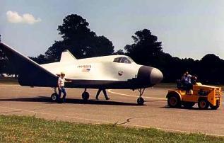
This concept, designated the HL-20, was designed for low operations cost, improved flight safety and conventional runway landings. The proposed Personnel Launch System (PLS), would utilize the HL-20 and an expendable launch system to provide manned access complementing the Space Shuttle. A full-size engineering research model of the HL-20 was constructed by the students and faculty of North Carolina State University and North Carolina A & T University for studying crew seating arrangements, habitability, equipment layout and crew ingress and egress. This engineering research model was 8.84 m long and provided the full-scale external and internal definition of the HL-20 for studies at the Langley Research Center.
The PLS mission was to transport people and small amounts of cargo to and from low-Earth orbit. Although not approved for development, the PLS was designed as a complement to the Space Shuttle and was considered for addition to the manned launch capability of the United States for three main reasons:
•Assured manned access to space. In that era of Space Station Freedom and subsequent missions of the Space Exploration Initiative, it was felt to be imperative that the United States have an alternate means of getting people and valuable small cargo to low-Earth orbit and back should the Space Shuttle be unavailable.
•Enhanced crew safety. Unlike the Space Shuttle, the PLS would not have main propulsion engines or a large payload bay. By removing large payload-carrying requirements from personnel delivery missions, the PLS would be a small, compact vehicle. It was then more feasible to design an abort capability to safely recover the crew during critical phases of the launch and return from orbit.
•Affordable costs. As a small vehicle designed with available technologies, the PLS was forecast to have a low development cost. Subsystem simplification and an aircraft approach to PLS ground and flight operations would also greatly lower the costs of operating PLS.
Candidate Shapes
The two designs considered for PLS differed in their aerodynamic characteristics and mission capabilities. The Johnson Space Center's approach used a ballistic bi-conic design shape (L/D of .75 to 1.0) with a parafoil for a precision landing. The Langley Research Center's HL-20 design was a lifting body that could make a conventional runway landing on return from orbit.
History of Lifting-Body Research
Predating and influencing the design of the Space Shuttle, several lifting body craft including M2-F2, M2-F3, HL-10, X-24A, and X-24B were flown by test pilots during the period 1966-1975. The M2-F2 and the HL-10 were proposed in the 1960s to carry 12 people to a space station following launch on a Saturn IB. In the Soviet Union, the BOR-4 shape was developed and studied by Langley based on recovery photographs. The HL-20 PLS concept evolved from the BOR-4 with modifications based on experience with the early US shapes. The "HL" designation stands for horizontal lander, and "20" reflected Langley's long-term involvement with the lifting body concept, which included the Northrop HL-10.
Advantages of Lifting Bodies
A lifting-body spacecraft, such as the HL-20, would have several advantages over other shapes. With higher lift characteristics during flight through the atmosphere while returning from orbit, the spacecraft could reach more land area, and the number of available landing opportunities to specific sites would be increased. Loads during entry, in terms of g-forces, would be limited to about 1.5 G's. This was important when returning sick, injured, or deconditioned Space Station crew members to Earth. Wheeled runway landings would be possible, permitting simple, precision recovery at many sites around the world, including the Kennedy Space Center launch site.
HL-20 PLS Missions
Delivery of passengers to Space Station Freedom would be the primary mission of a PLS. For the baseline space station mission, the crew size would be eight passengers (a space station crew) and two flight crew members.
A typical PLS mission operation scenario, using an HL-20, would commence at the Kennedy Space Center with the HL-20 being processed horizontally in a vehicle processing facility while an expendable launch vehicle was processed vertically in a separate facility. The launch vehicle and HL-20 would be mated at the launch pad and the launch sequence initiated as the space station passed over the launch site.
Following launch, the HL-20 would initially enter a low 185 km orbit to chase after the space station and then transfer up to the space station orbit altitude of 410 km. After rendezvous and docking at Space Station Freedom, crews would be exchanged, followed by a HL-20 return to Earth at the earliest opportunity.
The HL-20 would land horizontally on a runway in manner similar to the Space Shuttle. Total mission duration would not exceed 72 hours.
Other potential missions defined for a PLS included the orbital rescue of stranded astronauts, priority delivery and observation missions, and missions to perform satellite servicing. For these other missions, the basic HL-20 design would be unchanged, but interior subsystems and arrangements would be modified according to crew accommodations, duration, and equipment required for the particular mission.
HL-20 PLS Launch Vehicles
The HL-20 concept of the PLS was adaptable to several launch vehicle concepts. Titan III was an existing booster system which could be used for unmanned prototype launches but would require modification to be used as a manned system. A future launch system option at that time was the National Launch System under study by the Air Force and NASA. Choice of a launch system for the HL-20 PLS would depend both on the required date of initial PLS operations and the cost of booster development and launches.
Design Features
The design philosophy of the HL-20 PLS concept was to complement the Space Shuttle with safe, reliable manned transportation at the lowest cost. Of utmost importance was crew safety with emphasis being given in the HL-20 design to launch abort situations and the protection of the crew during vehicle recovery. Other requirements focused on minimizing life-cycle costs of the system by insuring simple operations, low-cost manufacturing, and high utilization potential.
With an overall length of 8.84 m and span across the wing tips of 7.16 m, the HL-20 PLS concept would be a much smaller craft than the Space Shuttle Orbiter. In fact, the HL-20 could fit within the payload bay of the Shuttle with wings folded. Overall, the HL-20 would weigh 10,000 kg without crew compared to the Space Shuttle Orbiter's empty weight of 84,000 kg. The space available inside for the crew and passengers, although less than the Shuttle, would be more than found in today's small corporate business jets.
A very important aspect of the HL-20 PLS concept which would help insure low cost operations was its design for maintainability. Large exterior access panels permitted technicians easy access to subsystems which would be exposed and easily replaced if required. The vehicle would be processed in a horizontal position. Selection and design of subsystems would emphasize simplicity and reduce maintenance requirements. For example, hydraulic systems would be replaced by all-electric controls. Unlike the Space Shuttle, the HL-20 would not have a payload bay or main engine propulsion, thereby reducing the processing time. The thermal protection system would be similar to the Space Shuttle's, but the much smaller size of the HL-20 would result in major reductions in inspection and maintenance times. These design changes and subsystem simplifications, along with the adoption of aircraft maintenance philosophies, could reduce the HL-20 processing man-hours to less than 10 percent of that used for the Space Shuttle Orbiter.
The design of the HL-20 PLS concept had taken into account crew safety and survivability for various abort modes. The interior layout with a ladder and hatch arrangement was designed to permit rapid egress of passengers and crew for emergencies on the launch pad. For on-the-pad emergencies or during launch where time was a critical element (launch vehicle fire or explosion), the HL-20 would be equipped with emergency escape rockets that would rapidly thrust the PLS away from the booster. The method was similar to that used during the Apollo program. Once at a safe distance, a cluster of three emergency parachutes would open to lower the vehicle to a safe ocean landing. Inflatable flotation devices ensured that it rode high in the water, with at least one of two hatches available for crew emergency egress.
HL-20 Lifting-Body Research
A significant amount of research effort went into experimental and computational investigations of the baseline HL-20 shape. The goal was to amass a data base of information about the system to aid in management decisions for PLS development.
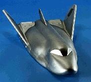
Using the extensive wind tunnel resources at Langley, researchers compiled a comprehensive aerodynamic and aerothermodynamic data base on the HL-20 concept spanning the entire speed range the PLS would fly through. Several models were built for testing in the various tunnels ranging from a 1.5 m model used for force and moment tests at low speeds to 15 cm models used in hypersonic tests. Results showed the shape possesses good flying qualities in all flight regimes. In addition to measurements of aerodynamic properties, experimental aerothermodynamic heating studies were performed. A new thermographic phosphor technique was used to study the heat transfer characteristics of a HL-20 model in high-speed wind tunnel tests. The model, coated with a phosphor, radiated at varying color intensities as a function of temperature during test when illuminated by ultra-violet light.
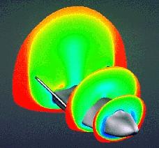
Computational fluid dynamics (CFD) codes, which mathematically simulate the flow field in the vicinity of the HL-20, were also used at Langley. These advanced computational grid techniques were used in conjunction with wind tunnel tests to study patterns of flow field phenomena, shock waves, stability and control and heating on the windward and leeward surfaces of the vehicle. Such computational analyses become critical in regimes where wind tunnels cannot duplicate the entry environment. For example, heating in the flight environment on this concept was predicted to be within the limits of Space Shuttle-based high-temperature, reusable surface insulation (HRSI) everywhere except at the nose of the vehicle, where Shuttle-based carbon-carbon thermal protection was required.
Two of the major questions that had to be answered about the lifting-body concept were how to control the HL-20 during the high-heating portion of the re-entry from orbit, and what was the proper guidance scheme for use in the landing phase to enhance its flying qualities. Langley researchers used a six-degree-of-freedom trajectory analysis technique along with mass, inertia and aerodynamic properties of the vehicle to investigate the entry phase of flight.
Results showed that the concept could be controlled through the hypersonic entry using only 14 kg of reaction control thruster fuel in nominal cases, or less than 90 kg of fuel in cases where the vehicle centre of gravity was offset and the upper atmosphere density and wind profiles were off-nominal. The entry analysis also showed the effects of using the vehicle's aerodynamic surfaces in conjunction with thrusters for control purposes.
In addition to computer modeling of vehicle controllability during entry, a flight simulator was set up at Langley to permit pilots to study the final landing phase of flight. Starting at an altitude of 4,600 m, the simulation presented the pilot with a realistic view of the approach to a runway landing. Using a side-stick controller, pilots, including one who had flown the X-15 rocketplane and the lifting bodies, demonstrated this configuration to be controllable and capable of pinpoint landings.
In October 1989, Rockwell International (Space Systems Division) began a year-long contracted effort managed by Langley Research Center to perform an in-depth study of PLS design and operations with the HL-20 concept as a baseline for the study. Using a concurrent engineering approach, Rockwell factored supportable, efficient design and operations measured into a detailed, cost-effective design along with a manufacturing plan and operations assessment. A key finding of this study was the realization that while design and technological factors could reduce costs of a new manned space transportation system, further significant savings were possible only if a new operations philosophy was adopted -- treating PLS in a manner similar to an operational airliner rather than a research and development space vehicle.
In October 1991, the Lockheed Advanced Development Company began a study to determine the feasibility of developing a prototype and operational system. The study objectives were to assess technical attributes, to determine flight qualification requirements, and to develop cost and schedule estimates.
A co-operative agreement between NASA, North Carolina State University and North Carolina A&T University led to the construction of a full-scale model of the HL-20 PLS for further human factors research on the concept. Students at the universities, with requirements furnished by Langley and guidance from university instructors, designed the research model during their spring 1990 semester with construction following during the summer.
The human factors research objectives, using this model, were to assess crew ingress and egress operations, assess crew volume and habitability arrangements, and determine visibility requirements for the crew during critical docking and landing operations.
The testing, using Langley Research Center volunteers as subjects, was completed on the HL-20 model in December 1991. Langley volunteers, wearing non-pressurized flight suits and helmets, were put through a series of tests with the craft placed in both horizontal and vertical modes.
The horizontal study found, for example, that a 10-member crew had adequate volume to quickly and in an orderly manner get in and out of the spacecraft. The available volume and proximity to others was found to be more than reasonably acceptable for a 10-member crew. Recommendations for revision included: more side-head room for the last row of seats to accommodate those taller than 170 cm; a wider aisle; removable seats and more training could improve emergency personnel capabilities and performance; more downward viewing capability for the pilot; structural supported in the windows could reduce viewing; and the cockpit display and seat design must be integrated with window placement.
Testing the HL-20 in a vertical position as oriented for launch posed a new set of factors. Getting in and out of the spacecraft, for example, required climbing through a hatch and up or down a ladder. In the horizontal mode, crew members walked along an aisle leading through the tail, which would be the exit-entry path at a space station or on the ground after a runway landing.
Partial-pressure suits, borrowed from the Johnson Space Center in Houston, were used for part of the study. Participants noticed less head room and restricted movement with the bulkier and heavier suits.
The results of the human factors studies showed where improvements in the baseline HL-20 design were desirable. These improvements would have little impact on overall vehicle shape or aerodynamic performance.
In the end, space station Freedom became the International Space Station. As the initial crew emergency rescue vehicle, the Russian Soyuz spacecraft was selected. However NASA, looking for a higher-capacity alternative and concerned about reliable availability of the Soyuz in the future, did begin development of the X-38 CERV in 1997. The X-38 was however based on the Johnson concept of parachute-assisted landing, and used the pure-USA X-24 lifting body shape....
Characteristics
Crew Size: 10. Orbital Storage: 3.00 days. Habitable Volume: 16.40 m3. Crew: 1,270 kg (2,790 lb).
Gross mass: 10,884 kg (23,995 lb).
Payload: 545 kg (1,201 lb).
Height: 8.93 m (29.29 ft).
Span: 7.16 m (23.49 ft).
--------------------------------------------------------------------------------
--------------------------------------------------------------------------------
Associated Countries •USA
--------------------------------------------------------------------------------
See also •Manned
•Rescue BAIL OUT!
In the early 1960’s, in the hey-day of the X-20 Dynasoar, it seemed that the US military would naturally keep building military aerospacecraft that would just keep going higher and faster. It was also supposed that the pilot would have to be given the equivalent of an ejection seat - some means of bailing out of the spacecraft in case of catastrophic failure or enemy attack. More...
•Space station orbit
•Spaceplane
•US Rocketplanes
--------------------------------------------------------------------------------
Associated Launch Vehicles •Titan American orbital launch vehicle. The Titan launch vehicle family was developed by the United States Air Force to meet its medium lift requirements in the 1960's. The designs finally put into production were derived from the Titan II ICBM. Titan outlived the competing NASA Saturn I launch vehicle and the Space Shuttle for military launches. It was finally replaced by the USAF's EELV boosters, the Atlas V and Delta IV. Although conceived as a low-cost, quick-reaction system, Titan was not successful as a commercial launch vehicle. Air Force requirements growth over the years drove its costs up - the Ariane using similar technology provided lower-cost access to space. More...
--------------------------------------------------------------------------------
Associated Manufacturers and Agencies •NASA American agency overseeing development of rockets and spacecraft. National Aeronautics and Space Administration, USA, USA. More...
•NASA Houston American agency overseeing development of rockets and spacecraft. Houston, Houston, USA. More...
--------------------------------------------------------------------------------
Bibliography •"HL-20", Aviation Week and Space Technology, 1991-07-15, page 52.
•"HL-20 MODEL FOR PERSONNEL LAUNCH SYSTEM RESEARCH", NASA Facts On-Line, NF172
--------------------------------------------------------------------------------
--------------------------------------------------------------------------------
HL-20 Chronology
--------------------------------------------------------------------------------
1983 During the Year - . •NASA Langley begins studies leading to HL-20 - . Nation: USA. Spacecraft: HL-20; BOR-4. The Vehicle Analysis Branch began investigation of the Soviet BOR-4. Small models were tested in NASA wind tunnels and demonstrated that the vehicle had good aerodynamic characteristics throughout the speed range from orbital entry interface to low supersonic speeds. The Soviet design had a 2,040 km cross-range capability and an outstandingly benign thermal profile at peak heating conditions. Therefore Langley adopted it as a baseline for a Crew Emergency Rescue Vehicle to back-up or replace the shuttle after the 1986 Challenger accident.
--------------------------------------------------------------------------------
1989 October - . •Rockwell begins year-long contracted study of HL-20 - . Nation: USA. Spacecraft: HL-20; Space Station Freedom. Rockwell International (Space Systems Division) began a year-long contracted effort managed by Langley Research Center to perform an in-depth study of Personnel Logistics System design and operations with the HL-20 concept as a baseline. The spaceplane would supplement the shuttle in support of the Space Station Freedom.
--------------------------------------------------------------------------------
1991 October - . •Lockheed feasibility studies of HL-20 - . Nation: USA. Spacecraft: HL-20; Space Station Freedom. Lockheed Advanced Development Company began a study to determine the feasibility of developing a prototype and operational system. The study objectives were to assess technical attributes, to determine flight qualification requirements, and to develop cost and schedule estimates.
--------------------------------------------------------------------------------
1991 December - . •HL-20 Mock-up tests completed - . Nation: USA. Spacecraft: HL-20; X-38; X-24A; Space Station Freedom. NASA, North Carolina State University and North Carolina A&T University built a full-scale model of the HL-20 for human factors research on the concept. In the end, space station Freedom became the International Space Station. As the initial crew emergency rescue vehicle, the Russian Soyuz spacecraft was selected. However NASA, looking for a higher-capacity alternative and concerned about reliable availability of the Soyuz in the future, did begin development of the X-38 CERV in 1997. The X-38 was however based on the Johnson concept of parachute-assisted landing, and used the pure-USA X-24 lifting body shape....
--------------------------------------------------------------------------------
HL-20 Images
HL-20 3 view
3 view of the HL-20, also known as ACRV (Assured Crew Return Vehicle) and PLS (Personnel Launch System). NASA 1991 design for backup to space shuttle (in case it was abandoned) and/or as crew return vehicle from space station. Lifting body re-entry vehicle clearly based on Russian Spiral design.
Credit: © Mark Wade
--------------------------------------------------------------------------------
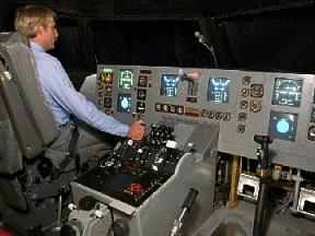
HL-20 Cockpit
Credit: NASA
--------------------------------------------------------------------------------
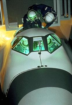
HL-20 Crew EVA
Credit: NASA
--------------------------------------------------------------------------------
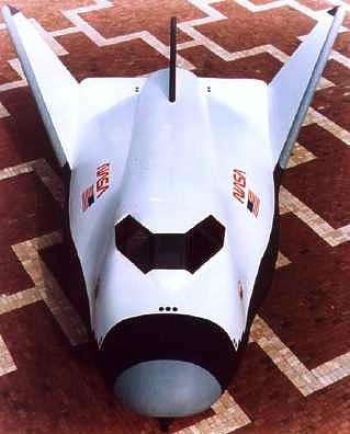
HL-20 Spaceplane
Credit: NASA
--------------------------------------------------------------------------------
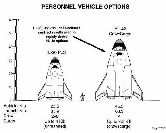
HL-20 / HL-42
HL-20 / HL-42 Comparison
Credit: NASA
--------------------------------------------------------------------------------
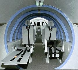
HL-20 Interior
Credit: NASA
--------------------------------------------------------------------------------
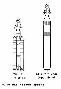
HL-20 Launch Vehicle
HL-20 Launch Vehicle Options
Credit: NASA
--------------------------------------------------------------------------------
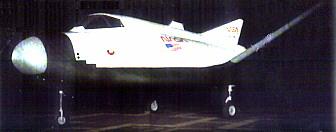
HL-20 Rollout
Credit: NASA
--------------------------------------------------------------------------------
HL-20 / BOR-4
HL-20 / BOR-4 Hypersonic Shockwave
Credit: NASA
--------------------------------------------------------------------------------
HL-20 / BOR-4
HL-20 / BOR-4 Wind Tunnel Model
Credit: NASA
***************************************************************
Copper Canyon
American manned spaceplane. Study 1984. DARPA program of 1984 that proved the technologies and concept for the X-30 National Aerospace Plane concept.
Copper Canyon was a Defense Advanced Research Projects Agency program of 1984 that studied an air-breathing SSTO concept. The concept was considered validated and led to the X-30 National Aerospace Plane project of 1986, at the expense of the USAF AMSC. Concepts used in the X-30 included new materials, structures, and manufacturing processes. These included a composite hydrogen tank, a propellant utilization fraction of 0.74, carbon-carbon aerodynamic surfaces, high temperature heat pipe sharp leading edges, use of computational flow dynamics to model the aerodynamic shape, and slush hydrogen as a fuel.
Crew Size: 1.
--------------------------------------------------------------------------------
--------------------------------------------------------------------------------
Associated Countries •USA
--------------------------------------------------------------------------------
See also •Low earth orbit
•Manned
•Spaceplane
•US Rocketplanes
--------------------------------------------------------------------------------
Associated Launch Vehicles •Copper Canyon American winged orbital launch vehicle. DARPA program of 1984 that proved the technologies and concept for the X-30 National Aerospace Plane concept
**************************************************************
TAV
American manned spaceplane. Developed in the 1980s but halted in favor of the X-30. USAF program of the 1980's that reached the test hardware stage and was leading to a single-stage-to-orbit, rocket-powered, winged manned vehicle.
Halted in favor of the X-30 National Aerospace Plane.
The Air Force's classified Trans-Atmospheric Vehicle development of the 1980's originated with the AMSC (Advanced Manned Spaceflight Capability) program of 1978. This studied the utility of manned spacecraft for military purposes. Trade studies were made of the technical alternates (one or two stages, vertical or winged horizontal takeoff and landing). The technical data generated during the Isinglass program of the 1960's was used as a starting point. The initial findings were positive, and it led to the following technology programs of the 1980's:
•Science Dawn, 1982 - Three in-depth preliminary designs were made by hand picked design teams. The vehicles would have used upgraded shuttle SSME engines. These would operate at 109% and 115% of nominal thrust, be modified for horizontal operation and be equipped with a two-position nozzle for higher specific impulse at high altitudes.
•Science Realm, 1984 - This phase resulted in design of a structural test article.
•Have Region, 1986 - This phase resulted in the actual manufacture and test of structural articles. Three structural concepts, were built. Two were considered partial successes, and one concept was considered completely validated. This used a stainless steel hydrogen tank liner and demonstrated a propellant utilization fraction of 0.88.
This classified work was replaced by the more ambitious air-breathing National Aerospace Plane project in 1986, which itself was finally cancelled due to lack of political support and technology challenges.
Characteristics
Crew Size: 1.
--------------------------------------------------------------------------------
--------------------------------------------------------------------------------
Associated Countries •USA
--------------------------------------------------------------------------------
See also •Low earth orbit
•Manned
•Spaceplane
•US Rocketplanes
****************************************************************
Sortie Vehicle
Sortie Vehicle
Cutaway view of Boeing 747-launched Sortie Vehicle, DARPA concept of mid-1980's
Credit: Boeing
***************************************************************
HL-20
HL-20 lifting body
The "luxury" crew rescue vehicle option was the Langley Research Center's $2-billion HL-20 which was loosely based on a Soviet spaceplane design.
Credit: NASA
American manned spaceplane. Study 1988. The HL-20 was a NASA Langley design for a manned spaceplane as a backup to the space shuttle (in case it was abandoned or grounded) and as a CERV (Crew Emergency Return Vehicle) for the Freedom space station.
Also known as the ACRV (Assured Crew Return Vehicle) or PLS (Personnel Launch System). the HL-29 was a lifting body re-entry vehicle based on the Russian BOR-4 design. It was designed for two flight crew, eight passengers, and piloted landing at airfield on landing gear. The HL-20 was studied by contractors and a full size mock-up was built. However the design was not selected for further development. Soyuz was designated as the International Space Station CERV. When doubts about the availability of Soyuz developed in 1995, NASA proceeded with development of the X-38, a NASA Johnson concept - a smaller version of the X-24 lifting body with a parafoil.
During launch a fairing from the Titan IV booster to the spacecraft would have had solid rocket motors (154,000 kgf) for launch abort, with parachutes for a tail-down water landing.
History
In 1983, the Vehicle Analysis Branch began the investigation of the BOR-4 small spaceplane being orbited several times by the Soviets starting in 1982 and recovered in the Indian Ocean and Black Sea. During recovery operations of the space plane in the Indian Ocean, an Australian P-3 Orion aircraft obtained photographs of the vehicle both floating in the water and being hauled aboard the recovery ship. This provided valuable insights into the shape, weight and centre of gravity of the vehicle. Based on this information, small wind tunnels models were produced and tested in the NASA Langley wind tunnels. The results demonstrated the vehicle had good aerodynamic characteristics throughout the speed range from orbital entry interface to low supersonic speeds. Wind tunnel tests showed configuration directional stability at all speeds from subsonic to Mach 20, trimmed to maximum L/D with 10 degree elevon deflections in subsonic range, with no control deflection at Mach 0.6 to 0.9, at 3 degree angle of attack in transonic range, and then again with no deflection from Mach 2.0 to Mach 20. The Soviet design had a 2,040 km cross-range capability and an outstandingly benign thermal profile at peak heating conditions.
Langley Research Center (LaRC) continued to investigate the aerodynamic characteristics of this shape and examined some shape changes to improve the low speed aerodynamics from transonic down to subsonic speeds. LaRC personnel who had worked in the 1960's on lifting bodies, especially the HL-10, were available to conduct these aerodynamic and shape modification tests.
Crew Emergency Rescue Vehicle
As a result of the 1986 Space Shuttle Challenger accident, interest rapidly developed in developing a crew emergency rescue vehicle (CERV) for the proposed US/International space station. If the Shuttle was unavailable for use or station astronauts had to return to Earth in an emergency this would provide continued manned assured access to space. In late 1986, Langley began to study the use of the BOR-4 lifting body shape as a CERV. This involved internal layouts, weight estimations, and centre-of-gravity estimates for a vehicle of large enough scale to accommodate up to 8 space station crew members.
This concept, designated the HL-20, was designed for low operations cost, improved flight safety and conventional runway landings. The proposed Personnel Launch System (PLS), would utilize the HL-20 and an expendable launch system to provide manned access complementing the Space Shuttle. A full-size engineering research model of the HL-20 was constructed by the students and faculty of North Carolina State University and North Carolina A & T University for studying crew seating arrangements, habitability, equipment layout and crew ingress and egress. This engineering research model was 8.84 m long and provided the full-scale external and internal definition of the HL-20 for studies at the Langley Research Center.
The PLS mission was to transport people and small amounts of cargo to and from low-Earth orbit. Although not approved for development, the PLS was designed as a complement to the Space Shuttle and was considered for addition to the manned launch capability of the United States for three main reasons:
•Assured manned access to space. In that era of Space Station Freedom and subsequent missions of the Space Exploration Initiative, it was felt to be imperative that the United States have an alternate means of getting people and valuable small cargo to low-Earth orbit and back should the Space Shuttle be unavailable.
•Enhanced crew safety. Unlike the Space Shuttle, the PLS would not have main propulsion engines or a large payload bay. By removing large payload-carrying requirements from personnel delivery missions, the PLS would be a small, compact vehicle. It was then more feasible to design an abort capability to safely recover the crew during critical phases of the launch and return from orbit.
•Affordable costs. As a small vehicle designed with available technologies, the PLS was forecast to have a low development cost. Subsystem simplification and an aircraft approach to PLS ground and flight operations would also greatly lower the costs of operating PLS.
Candidate Shapes
The two designs considered for PLS differed in their aerodynamic characteristics and mission capabilities. The Johnson Space Center's approach used a ballistic bi-conic design shape (L/D of .75 to 1.0) with a parafoil for a precision landing. The Langley Research Center's HL-20 design was a lifting body that could make a conventional runway landing on return from orbit.
History of Lifting-Body Research
Predating and influencing the design of the Space Shuttle, several lifting body craft including M2-F2, M2-F3, HL-10, X-24A, and X-24B were flown by test pilots during the period 1966-1975. The M2-F2 and the HL-10 were proposed in the 1960s to carry 12 people to a space station following launch on a Saturn IB. In the Soviet Union, the BOR-4 shape was developed and studied by Langley based on recovery photographs. The HL-20 PLS concept evolved from the BOR-4 with modifications based on experience with the early US shapes. The "HL" designation stands for horizontal lander, and "20" reflected Langley's long-term involvement with the lifting body concept, which included the Northrop HL-10.
Advantages of Lifting Bodies
A lifting-body spacecraft, such as the HL-20, would have several advantages over other shapes. With higher lift characteristics during flight through the atmosphere while returning from orbit, the spacecraft could reach more land area, and the number of available landing opportunities to specific sites would be increased. Loads during entry, in terms of g-forces, would be limited to about 1.5 G's. This was important when returning sick, injured, or deconditioned Space Station crew members to Earth. Wheeled runway landings would be possible, permitting simple, precision recovery at many sites around the world, including the Kennedy Space Center launch site.
HL-20 PLS Missions
Delivery of passengers to Space Station Freedom would be the primary mission of a PLS. For the baseline space station mission, the crew size would be eight passengers (a space station crew) and two flight crew members.
A typical PLS mission operation scenario, using an HL-20, would commence at the Kennedy Space Center with the HL-20 being processed horizontally in a vehicle processing facility while an expendable launch vehicle was processed vertically in a separate facility. The launch vehicle and HL-20 would be mated at the launch pad and the launch sequence initiated as the space station passed over the launch site.
Following launch, the HL-20 would initially enter a low 185 km orbit to chase after the space station and then transfer up to the space station orbit altitude of 410 km. After rendezvous and docking at Space Station Freedom, crews would be exchanged, followed by a HL-20 return to Earth at the earliest opportunity.
The HL-20 would land horizontally on a runway in manner similar to the Space Shuttle. Total mission duration would not exceed 72 hours.
Other potential missions defined for a PLS included the orbital rescue of stranded astronauts, priority delivery and observation missions, and missions to perform satellite servicing. For these other missions, the basic HL-20 design would be unchanged, but interior subsystems and arrangements would be modified according to crew accommodations, duration, and equipment required for the particular mission.
HL-20 PLS Launch Vehicles
The HL-20 concept of the PLS was adaptable to several launch vehicle concepts. Titan III was an existing booster system which could be used for unmanned prototype launches but would require modification to be used as a manned system. A future launch system option at that time was the National Launch System under study by the Air Force and NASA. Choice of a launch system for the HL-20 PLS would depend both on the required date of initial PLS operations and the cost of booster development and launches.
Design Features
The design philosophy of the HL-20 PLS concept was to complement the Space Shuttle with safe, reliable manned transportation at the lowest cost. Of utmost importance was crew safety with emphasis being given in the HL-20 design to launch abort situations and the protection of the crew during vehicle recovery. Other requirements focused on minimizing life-cycle costs of the system by insuring simple operations, low-cost manufacturing, and high utilization potential.
With an overall length of 8.84 m and span across the wing tips of 7.16 m, the HL-20 PLS concept would be a much smaller craft than the Space Shuttle Orbiter. In fact, the HL-20 could fit within the payload bay of the Shuttle with wings folded. Overall, the HL-20 would weigh 10,000 kg without crew compared to the Space Shuttle Orbiter's empty weight of 84,000 kg. The space available inside for the crew and passengers, although less than the Shuttle, would be more than found in today's small corporate business jets.
A very important aspect of the HL-20 PLS concept which would help insure low cost operations was its design for maintainability. Large exterior access panels permitted technicians easy access to subsystems which would be exposed and easily replaced if required. The vehicle would be processed in a horizontal position. Selection and design of subsystems would emphasize simplicity and reduce maintenance requirements. For example, hydraulic systems would be replaced by all-electric controls. Unlike the Space Shuttle, the HL-20 would not have a payload bay or main engine propulsion, thereby reducing the processing time. The thermal protection system would be similar to the Space Shuttle's, but the much smaller size of the HL-20 would result in major reductions in inspection and maintenance times. These design changes and subsystem simplifications, along with the adoption of aircraft maintenance philosophies, could reduce the HL-20 processing man-hours to less than 10 percent of that used for the Space Shuttle Orbiter.
The design of the HL-20 PLS concept had taken into account crew safety and survivability for various abort modes. The interior layout with a ladder and hatch arrangement was designed to permit rapid egress of passengers and crew for emergencies on the launch pad. For on-the-pad emergencies or during launch where time was a critical element (launch vehicle fire or explosion), the HL-20 would be equipped with emergency escape rockets that would rapidly thrust the PLS away from the booster. The method was similar to that used during the Apollo program. Once at a safe distance, a cluster of three emergency parachutes would open to lower the vehicle to a safe ocean landing. Inflatable flotation devices ensured that it rode high in the water, with at least one of two hatches available for crew emergency egress.
HL-20 Lifting-Body Research
A significant amount of research effort went into experimental and computational investigations of the baseline HL-20 shape. The goal was to amass a data base of information about the system to aid in management decisions for PLS development.
Using the extensive wind tunnel resources at Langley, researchers compiled a comprehensive aerodynamic and aerothermodynamic data base on the HL-20 concept spanning the entire speed range the PLS would fly through. Several models were built for testing in the various tunnels ranging from a 1.5 m model used for force and moment tests at low speeds to 15 cm models used in hypersonic tests. Results showed the shape possesses good flying qualities in all flight regimes. In addition to measurements of aerodynamic properties, experimental aerothermodynamic heating studies were performed. A new thermographic phosphor technique was used to study the heat transfer characteristics of a HL-20 model in high-speed wind tunnel tests. The model, coated with a phosphor, radiated at varying color intensities as a function of temperature during test when illuminated by ultra-violet light.
Computational fluid dynamics (CFD) codes, which mathematically simulate the flow field in the vicinity of the HL-20, were also used at Langley. These advanced computational grid techniques were used in conjunction with wind tunnel tests to study patterns of flow field phenomena, shock waves, stability and control and heating on the windward and leeward surfaces of the vehicle. Such computational analyses become critical in regimes where wind tunnels cannot duplicate the entry environment. For example, heating in the flight environment on this concept was predicted to be within the limits of Space Shuttle-based high-temperature, reusable surface insulation (HRSI) everywhere except at the nose of the vehicle, where Shuttle-based carbon-carbon thermal protection was required.
Two of the major questions that had to be answered about the lifting-body concept were how to control the HL-20 during the high-heating portion of the re-entry from orbit, and what was the proper guidance scheme for use in the landing phase to enhance its flying qualities. Langley researchers used a six-degree-of-freedom trajectory analysis technique along with mass, inertia and aerodynamic properties of the vehicle to investigate the entry phase of flight.
Results showed that the concept could be controlled through the hypersonic entry using only 14 kg of reaction control thruster fuel in nominal cases, or less than 90 kg of fuel in cases where the vehicle centre of gravity was offset and the upper atmosphere density and wind profiles were off-nominal. The entry analysis also showed the effects of using the vehicle's aerodynamic surfaces in conjunction with thrusters for control purposes.
In addition to computer modeling of vehicle controllability during entry, a flight simulator was set up at Langley to permit pilots to study the final landing phase of flight. Starting at an altitude of 4,600 m, the simulation presented the pilot with a realistic view of the approach to a runway landing. Using a side-stick controller, pilots, including one who had flown the X-15 rocketplane and the lifting bodies, demonstrated this configuration to be controllable and capable of pinpoint landings.
In October 1989, Rockwell International (Space Systems Division) began a year-long contracted effort managed by Langley Research Center to perform an in-depth study of PLS design and operations with the HL-20 concept as a baseline for the study. Using a concurrent engineering approach, Rockwell factored supportable, efficient design and operations measured into a detailed, cost-effective design along with a manufacturing plan and operations assessment. A key finding of this study was the realization that while design and technological factors could reduce costs of a new manned space transportation system, further significant savings were possible only if a new operations philosophy was adopted -- treating PLS in a manner similar to an operational airliner rather than a research and development space vehicle.
In October 1991, the Lockheed Advanced Development Company began a study to determine the feasibility of developing a prototype and operational system. The study objectives were to assess technical attributes, to determine flight qualification requirements, and to develop cost and schedule estimates.
A co-operative agreement between NASA, North Carolina State University and North Carolina A&T University led to the construction of a full-scale model of the HL-20 PLS for further human factors research on the concept. Students at the universities, with requirements furnished by Langley and guidance from university instructors, designed the research model during their spring 1990 semester with construction following during the summer.
The human factors research objectives, using this model, were to assess crew ingress and egress operations, assess crew volume and habitability arrangements, and determine visibility requirements for the crew during critical docking and landing operations.
The testing, using Langley Research Center volunteers as subjects, was completed on the HL-20 model in December 1991. Langley volunteers, wearing non-pressurized flight suits and helmets, were put through a series of tests with the craft placed in both horizontal and vertical modes.
The horizontal study found, for example, that a 10-member crew had adequate volume to quickly and in an orderly manner get in and out of the spacecraft. The available volume and proximity to others was found to be more than reasonably acceptable for a 10-member crew. Recommendations for revision included: more side-head room for the last row of seats to accommodate those taller than 170 cm; a wider aisle; removable seats and more training could improve emergency personnel capabilities and performance; more downward viewing capability for the pilot; structural supported in the windows could reduce viewing; and the cockpit display and seat design must be integrated with window placement.
Testing the HL-20 in a vertical position as oriented for launch posed a new set of factors. Getting in and out of the spacecraft, for example, required climbing through a hatch and up or down a ladder. In the horizontal mode, crew members walked along an aisle leading through the tail, which would be the exit-entry path at a space station or on the ground after a runway landing.
Partial-pressure suits, borrowed from the Johnson Space Center in Houston, were used for part of the study. Participants noticed less head room and restricted movement with the bulkier and heavier suits.
The results of the human factors studies showed where improvements in the baseline HL-20 design were desirable. These improvements would have little impact on overall vehicle shape or aerodynamic performance.
In the end, space station Freedom became the International Space Station. As the initial crew emergency rescue vehicle, the Russian Soyuz spacecraft was selected. However NASA, looking for a higher-capacity alternative and concerned about reliable availability of the Soyuz in the future, did begin development of the X-38 CERV in 1997. The X-38 was however based on the Johnson concept of parachute-assisted landing, and used the pure-USA X-24 lifting body shape....
Characteristics
Crew Size: 10. Orbital Storage: 3.00 days. Habitable Volume: 16.40 m3. Crew: 1,270 kg (2,790 lb).
Gross mass: 10,884 kg (23,995 lb).
Payload: 545 kg (1,201 lb).
Height: 8.93 m (29.29 ft).
Span: 7.16 m (23.49 ft).
--------------------------------------------------------------------------------
--------------------------------------------------------------------------------
Associated Countries •USA
--------------------------------------------------------------------------------
See also •Manned
•Rescue BAIL OUT!
In the early 1960’s, in the hey-day of the X-20 Dynasoar, it seemed that the US military would naturally keep building military aerospacecraft that would just keep going higher and faster. It was also supposed that the pilot would have to be given the equivalent of an ejection seat - some means of bailing out of the spacecraft in case of catastrophic failure or enemy attack. More...
•Space station orbit
•Spaceplane
•US Rocketplanes
--------------------------------------------------------------------------------
Associated Launch Vehicles •Titan American orbital launch vehicle. The Titan launch vehicle family was developed by the United States Air Force to meet its medium lift requirements in the 1960's. The designs finally put into production were derived from the Titan II ICBM. Titan outlived the competing NASA Saturn I launch vehicle and the Space Shuttle for military launches. It was finally replaced by the USAF's EELV boosters, the Atlas V and Delta IV. Although conceived as a low-cost, quick-reaction system, Titan was not successful as a commercial launch vehicle. Air Force requirements growth over the years drove its costs up - the Ariane using similar technology provided lower-cost access to space. More...
--------------------------------------------------------------------------------
Associated Manufacturers and Agencies •NASA American agency overseeing development of rockets and spacecraft. National Aeronautics and Space Administration, USA, USA. More...
•NASA Houston American agency overseeing development of rockets and spacecraft. Houston, Houston, USA. More...
--------------------------------------------------------------------------------
Bibliography •"HL-20", Aviation Week and Space Technology, 1991-07-15, page 52.
•"HL-20 MODEL FOR PERSONNEL LAUNCH SYSTEM RESEARCH", NASA Facts On-Line, NF172
--------------------------------------------------------------------------------
--------------------------------------------------------------------------------
HL-20 Chronology
--------------------------------------------------------------------------------
1983 During the Year - . •NASA Langley begins studies leading to HL-20 - . Nation: USA. Spacecraft: HL-20; BOR-4. The Vehicle Analysis Branch began investigation of the Soviet BOR-4. Small models were tested in NASA wind tunnels and demonstrated that the vehicle had good aerodynamic characteristics throughout the speed range from orbital entry interface to low supersonic speeds. The Soviet design had a 2,040 km cross-range capability and an outstandingly benign thermal profile at peak heating conditions. Therefore Langley adopted it as a baseline for a Crew Emergency Rescue Vehicle to back-up or replace the shuttle after the 1986 Challenger accident.
--------------------------------------------------------------------------------
1989 October - . •Rockwell begins year-long contracted study of HL-20 - . Nation: USA. Spacecraft: HL-20; Space Station Freedom. Rockwell International (Space Systems Division) began a year-long contracted effort managed by Langley Research Center to perform an in-depth study of Personnel Logistics System design and operations with the HL-20 concept as a baseline. The spaceplane would supplement the shuttle in support of the Space Station Freedom.
--------------------------------------------------------------------------------
1991 October - . •Lockheed feasibility studies of HL-20 - . Nation: USA. Spacecraft: HL-20; Space Station Freedom. Lockheed Advanced Development Company began a study to determine the feasibility of developing a prototype and operational system. The study objectives were to assess technical attributes, to determine flight qualification requirements, and to develop cost and schedule estimates.
--------------------------------------------------------------------------------
1991 December - . •HL-20 Mock-up tests completed - . Nation: USA. Spacecraft: HL-20; X-38; X-24A; Space Station Freedom. NASA, North Carolina State University and North Carolina A&T University built a full-scale model of the HL-20 for human factors research on the concept. In the end, space station Freedom became the International Space Station. As the initial crew emergency rescue vehicle, the Russian Soyuz spacecraft was selected. However NASA, looking for a higher-capacity alternative and concerned about reliable availability of the Soyuz in the future, did begin development of the X-38 CERV in 1997. The X-38 was however based on the Johnson concept of parachute-assisted landing, and used the pure-USA X-24 lifting body shape....
--------------------------------------------------------------------------------
HL-20 Images
HL-20 3 view
3 view of the HL-20, also known as ACRV (Assured Crew Return Vehicle) and PLS (Personnel Launch System). NASA 1991 design for backup to space shuttle (in case it was abandoned) and/or as crew return vehicle from space station. Lifting body re-entry vehicle clearly based on Russian Spiral design.
Credit: © Mark Wade
--------------------------------------------------------------------------------
HL-20 Cockpit
Credit: NASA
--------------------------------------------------------------------------------
HL-20 Crew EVA
Credit: NASA
--------------------------------------------------------------------------------
HL-20 Spaceplane
Credit: NASA
--------------------------------------------------------------------------------
HL-20 / HL-42
HL-20 / HL-42 Comparison
Credit: NASA
--------------------------------------------------------------------------------
HL-20 Interior
Credit: NASA
--------------------------------------------------------------------------------
HL-20 Launch Vehicle
HL-20 Launch Vehicle Options
Credit: NASA
--------------------------------------------------------------------------------
HL-20 Rollout
Credit: NASA
--------------------------------------------------------------------------------
HL-20 / BOR-4
HL-20 / BOR-4 Hypersonic Shockwave
Credit: NASA
--------------------------------------------------------------------------------
HL-20 / BOR-4
HL-20 / BOR-4 Wind Tunnel Model
Credit: NASA
***************************************************************
Copper Canyon
American manned spaceplane. Study 1984. DARPA program of 1984 that proved the technologies and concept for the X-30 National Aerospace Plane concept.
Copper Canyon was a Defense Advanced Research Projects Agency program of 1984 that studied an air-breathing SSTO concept. The concept was considered validated and led to the X-30 National Aerospace Plane project of 1986, at the expense of the USAF AMSC. Concepts used in the X-30 included new materials, structures, and manufacturing processes. These included a composite hydrogen tank, a propellant utilization fraction of 0.74, carbon-carbon aerodynamic surfaces, high temperature heat pipe sharp leading edges, use of computational flow dynamics to model the aerodynamic shape, and slush hydrogen as a fuel.
Crew Size: 1.
--------------------------------------------------------------------------------
--------------------------------------------------------------------------------
Associated Countries •USA
--------------------------------------------------------------------------------
See also •Low earth orbit
•Manned
•Spaceplane
•US Rocketplanes
--------------------------------------------------------------------------------
Associated Launch Vehicles •Copper Canyon American winged orbital launch vehicle. DARPA program of 1984 that proved the technologies and concept for the X-30 National Aerospace Plane concept
**************************************************************
No comments:
Post a Comment