
The Northrop HL-10
From astronautix.com:
HL-10
HL-10 Lifting Body
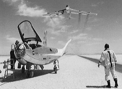
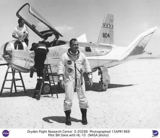
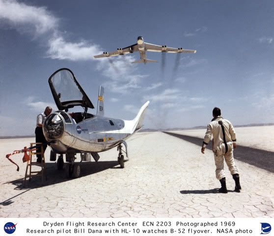
HL-10 Lifting Body with B-52 and Test Pilot Dana
Credit: NASA
American manned spaceplane. 37 launches, 1966.12.22 to 1970.07.17 . The HL-10 was the favored lifting body configuration of NASA Langley in the 1960's. It reached Mach 1.86 and 27,700 m during its flight tests.
This configuration was found to be the best of the lifting bodies, and it was used in several of the orbiter proposals in NASA's Phase A and Phase B shuttle design studies. It was also very similar to the winning X-33 configuration proposed by the Lockheed. Purportedly an unmanned test vehicle of this design was tested at orbital speeds by the US Air Force in a black Lockheed Skunk Work's project, possibly on two Titan 3B / Agena D launches in 1972.
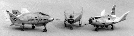
The HL-10 was one of five lifting body designs flown at NASA's Dryden Flight Research Center, Edwards, Calif., from July 1966 to November 1975 to study and validate the concept of safely maneuvering and landing a low lift-over-drag vehicle designed for reentry from space. It was now on permanent public display near the main entrance of Dryden.
The other designs were the M2-F2, M2-F3 (rebuilt M2-F2 following a landing accident), X-24A and X-24B (rebuilt X-24A with a different aerodynamic shape).
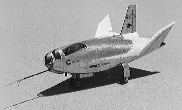
Wingless lifting bodies attained aerodynamic stability and lift from the shape of the vehicle. Lift resulted from more air pressure on the bottom of the body than on the top. They used energy and aerodynamic lift for in-flight maneuvering and a powerless, glider-like landing.
Background
The original idea of lifting bodies was conceived in 1957 by Dr. Alfred J. Eggers Jr., then the assistant director for Research and Development Analysis and Planning at NASA's Ames Research Center, Moffett Field, Calif.
The lifting body concept was originally tested at Dryden with a plywood prototype designated the M2-F1 and built in late 1962. It featured a plywood shell built by Gus Briegleb, a sailplane builder from Mirage Dry Lake, Calif., placed over a tubular frame built at Dryden. The M2-F1 was towed aloft, first behind an auto and then a C-47 more than 100 times, to validate basic lifting body stability and control characteristics. This led to establishment of the formal program which resulted in the HL-10 and its sister vehicles.
Northrop Corporation built the HL-10. The contract for construction of the HL-10 and the M2-F2, first of the fleet of lifting bodies flown at Dryden and also built by Northrop, was $1.8 million. "HL" stands for horizontal landing, and "10" refers to the tenth design studied by engineers at NASA's Langley Research Center, Hampton, Va.
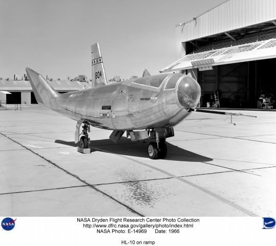
The HL-10 was delivered to NASA in January 1966. During the next 10 months it was instrumented for the research program and prepared for flight. The HL-10 and the M2-F2 were tested in wind tunnels at Ames Research Center before research flights began.
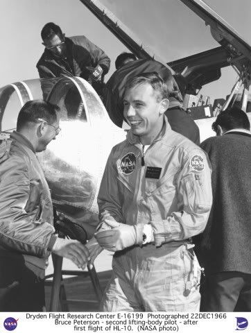
First flight of the HL-10 was on Dec. 22, 1966, with research pilot Bruce Peterson in the cockpit. Although an XLR-11 rocket engine was installed in the vehicle, the first 11 drop flights from the B-52 launch aircraft were powerless glide flights to assess handling qualities, stability, and control.
The HL-10 was flown 37 times during the lifting body research program and logged the highest altitude and fastest speed in the program. On Feb. 18, 1970, Air Force test pilot Peter Hoag piloted the HL-10 to Mach 1.86 (1,228 mph). Nine days later, NASA pilot Bill Dana flew the vehicle to 90,030 feet, which became the highest altitude reached in the program.
Typical Flight Profile
During a typical lifting body flight, the B-52 -- with the research vehicle attached to the pylon mount on the right wing between the fuselage and inboard engine pod -- flew to a height of about 45,000 feet and a launch speed of about 450 mph.
Moments after being dropped, the XLR-11 rocket engine (same type engine used in the Bell X-l) was ignited by the pilot. Speed and altitude increased until the engine was shut down by choice or fuel exhaustion, depending upon the individual mission profile. The lifting bodies normally carried enough fuel for about 100 seconds of powered flight and routinely reached altitudes of 50,000 to 80,000 feet and speeds above Mach 1.
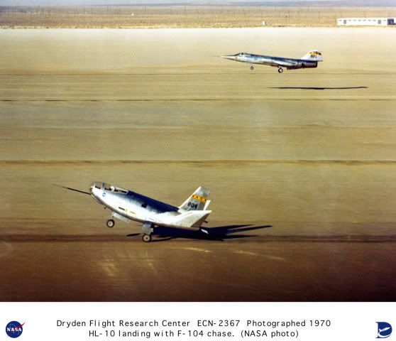
Following engine shutdown, the pilot maneuvered the vehicle through a simulated return-from-space corridor into a pre-planned approach for a landing on one of the lakebed runways on Rogers Dry Lake at Edwards. A circular approach was used to lose altitude during the landing phase. On the final approach leg, the pilot increased his rate of descent to build up energy. At about 100 feet altitude, a "flare out" maneuver dropped air speed to about 200 mph for the landing.
The HL-10 helped develop energy management and landing techniques used presently with the space shuttle orbiters.
Specifications
Dimensions: Length, 22 ft. 2 in.; Width, 15 ft. 7 in.; Height, 11 ft. 5 in.; Min. Weight, 5,265 lbs.; Max. Weight, 9,000 lbs (with water ballast tanks full).
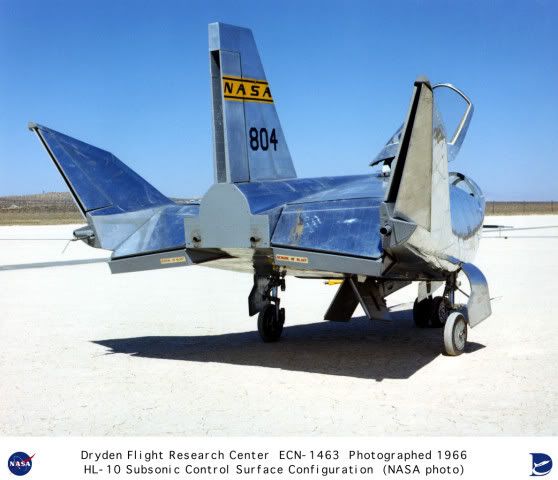
Controls: Elevons between vertical and center fins for pitch and roll control. Split rudder on center fin for yaw and speed control. All surfaces used in three-axis stabilizer-augmenter system.
Power: One XLR-11 four-chamber rocket engine fueled by ethyl alcohol and liquid oxygen, producing maximum of 6,000 lbs thrust; built by Chemical Reaction Motors, Inc.
Aux. Power: Silver zinc batteries provided electrical power for control system, flight instruments, radios, cockpit heat, and stability augmentation system. To assist in pre-landing flare, four throttleable hydrogen peroxide rockets provided up to 400 lbs of thrust.
Landing Gear: Main gear was modified T-38 system retracted manually, and lowered by nitrogen pressure. Nose gear was modified T-39 nose gear, retracted manually and lowered with nitrogen pressure.
Pilot Ejection System: Modified F-106 system.
Characteristics
Spacecraft delta v: 850 m/s (2,780 ft/sec).
Gross mass: 4,080 kg (8,990 lb).
Unfuelled mass: 2,780 kg (6,120 lb).
Height: 6.77 m (22.21 ft).
Span: 4.60 m (15.00 ft).
Thrust: 26.40 kN (5,935 lbf).
First date: 12/22/1966 .
Last date: 7/17/1970 .
Number: 37 .
--------------------------------------------------------------------------------
--------------------------------------------------------------------------------
Associated Countries •USA
--------------------------------------------------------------------------------
Associated Engines •XLR11 Reaction Motors, Thiokol Lox/Alcohol rocket engine. Out of Production. Launch thrust 26.67 kN. Rocket engine developed for X-1 in 1940s to break the sound barrier and used twenty years later to power experimental lifting bodies. Four combustion chambers. More...
--------------------------------------------------------------------------------
See also •Manned
•Spaceplane
•Suborbital
•US Rocketplanes
--------------------------------------------------------------------------------
Associated Manufacturers and Agencies •Northrop American manufacturer of rockets and spacecraft. Northrop, USA. More...
--------------------------------------------------------------------------------
Associated Propellants •Lox/Alcohol
--------------------------------------------------------------------------------
Bibliography •Gatland, Kenneth, Manned Spacecraft, Macmillan, New York, 1968.
•Miller, Jay,, The X-Planes, Aerofax, Arlington, Texas, 1988.
•Miller, Ron, The Dream Machines, Krieger, Malabar, Florida, 1993.
•Zhelyez x-plane book,
•Houchin II, Roy and Smith, Terry, "X-20 (7 articles)", Quest, 1994, Volume 3, Issue 4, page 4.
•Peebles, Curtis, "The Origins of the US Space Shuttle - 1", Spaceflight, 1979, Volume 21, page 435.
•NASA Dryden Flight Research Center Web Site, Web Address when accessed: http://www.dfrc.nasa.gov/.
•Grimwood, James M., Project Mercury: A Chronology, NASA Special Publication-4001.
•NASA Report, NASA Factsheet FS-010-DFRC HL-10, Web Address when accessed: http://www.dfrc.nasa.gov/Newsroom/FactSheets/PDF/FS-010-DFRC.pdf.
•NASA Report, Full scale wind tunnel investigation of the HL-10 manned lifting body flight vehicle, Web Address when accessed: http://ntrs.nasa.gov/archive/nasa/casi.ntrs.nasa.gov/19710070745_1971070745.pdf.
•NASA Report, Developing and Flight Testing the HL-10 Lifting Body: A Precursor to the Space Shuttle, Web Address when accessed: http://dtrs.dfrc.nasa.gov/archive/00000234/01/RP1332.pdf.
•NASA Report, Developing and flight testing the HL-10 lifting body: A precursor to the Space Shuttle, Web Address when accessed: http://ntrs.nasa.gov/archive/nasa/casi.ntrs.nasa.gov/19940030197_1994030197.pdf.
•NASA Report, Landing characteristics of a dynamic model of the HL-10 manned lifting entry vehicle, Web Address when accessed: http://ntrs.nasa.gov/archive/nasa/casi.ntrs.nasa.gov/19670001463_1967001463.pdf.
--------------------------------------------------------------------------------
--------------------------------------------------------------------------------
HL-10 Chronology
--------------------------------------------------------------------------------
1957 July - August - . •Semiballistic design for a manned reentry spacecraft. - . Nation: USA. Spacecraft: X-24A; HL-10. Summary: Alfred J. Eggers, Jr., of the NACA Ames Aeronautical Laboratory, worked out a semiballistic design for a manned reentry spacecraft..
--------------------------------------------------------------------------------
1962 September - . •M2-F1 lifting body first flight. - . Nation: USA. Spacecraft: M2-F2; HL-10; X-24A. The lifting body concept was first tested at Dryden with a plywood prototype designated the M2-F1 built in late 1962. It featured a plywood shell built by Gus Briegleb, a sailplane builder from Mirage Dry Lake, Calif., placed over a tubular frame built at Dryden. The M2-F1 was towed aloft, first behind an auto and then a C-47 more than 100 times, to validate basic lifting body stability and control characteristics. This led to establishment of the formal program which resulted in the HL-10, M2-F2, M2-F3, X-24A, and X-24B lifting bodies.
--------------------------------------------------------------------------------
1966 January - . •HL-10 delivered to NASA - . Nation: USA. Spacecraft: HL-10. Summary: During the next 10 months it was instrumented for the research program and prepared for flight. The HL-10 and the M2-F2 were tested in wind tunnels at Ames Research Center before research flights began..
--------------------------------------------------------------------------------
1966 December 22 - . •HL-10 Flight 1 - . Crew: Peterson, Bruce. Payload: HL-10 flight 1. Nation: USA. Related Persons: Peterson, Bruce. Program: NASA Lifting Body. Class: Manned. Type: Manned spaceplane. Spacecraft: HL-10. Summary: First flight HL-10. Maximum Speed - 735 kph. Maximum Altitude - 13720 m. Flight Time - 187 sec..
--------------------------------------------------------------------------------
1968 March 15 - . •HL-10 Flight 2 - . Crew: Gentry. Payload: HL-10 flight 2. Nation: USA. Related Persons: Gentry. Program: NASA Lifting Body. Class: Manned. Type: Manned spaceplane. Spacecraft: HL-10. Summary: Maximum Speed - 684 kph. Maximum Altitude - 13720 m. Flight Time - 243 sec..
--------------------------------------------------------------------------------
1968 April 3 - . •HL-10 Flight 3 - . Crew: Gentry. Payload: HL-10 flight 3. Nation: USA. Related Persons: Gentry. Program: NASA Lifting Body. Class: Manned. Type: Manned spaceplane. Spacecraft: HL-10. Summary: Maximum Speed - 732 kph. Maximum Altitude - 13720 m. Flight Time - 242 sec..
--------------------------------------------------------------------------------
1968 April 25 - . •HL-10 Flight 4 - . Crew: Gentry. Payload: HL-10 flight 4. Nation: USA. Related Persons: Gentry. Program: NASA Lifting Body. Class: Manned. Type: Manned spaceplane. Spacecraft: HL-10. Summary: Maximum Speed - 739 kph. Maximum Altitude - 13720 m. Flight Time - 258 sec..
--------------------------------------------------------------------------------
1968 May 3 - . •HL-10 Flight 5 - . Crew: Gentry. Payload: HL-10 flight 5. Nation: USA. Related Persons: Gentry. Program: NASA Lifting Body. Class: Manned. Type: Manned spaceplane. Spacecraft: HL-10. Summary: Maximum Speed - 732 kph. Maximum Altitude - 13720 m. Flight Time - 245 sec..
--------------------------------------------------------------------------------
1968 May 16 - . •HL-10 Flight 6 - . Crew: Gentry. Payload: HL-10 flight 6. Nation: USA. Related Persons: Gentry. Program: NASA Lifting Body. Class: Manned. Type: Manned spaceplane. Spacecraft: HL-10. Summary: Maximum Speed - 719 kph. Maximum Altitude - 13720 m. Flight Time - 265 sec..
--------------------------------------------------------------------------------
1968 May 28 - . •HL-10 Flight 7 - . Crew: Manke. Payload: HL-10 flight 7. Nation: USA. Related Persons: Manke. Program: NASA Lifting Body. Class: Manned. Type: Manned spaceplane. Spacecraft: HL-10. Summary: Maximum Speed - 698 kph. Maximum Altitude - 13720 m. Flight Time - 245 sec..
--------------------------------------------------------------------------------
1968 June 11 - . •HL-10 Flight 8 - . Crew: Manke. Payload: HL-10 flight 8. Nation: USA. Related Persons: Manke. Program: NASA Lifting Body. Class: Manned. Type: Manned spaceplane. Spacecraft: HL-10. Summary: Maximum Speed - 697 kph. Maximum Altitude - 13720 m. Flight Time - 246 sec..
--------------------------------------------------------------------------------
1968 June 21 - . •HL-10 Flight 9 - . Crew: Gentry. Payload: HL-10 flight 9. Nation: USA. Related Persons: Gentry. Program: NASA Lifting Body. Class: Manned. Type: Manned spaceplane. Spacecraft: HL-10. Summary: Maximum Speed - 681 kph. Maximum Altitude - 13720 m. Flight Time - 271 sec..
--------------------------------------------------------------------------------
1968 September 24 - . •HL-10 Flight 10 - . Crew: Gentry. Payload: HL-10 flight 10. Nation: USA. Related Persons: Gentry. Program: NASA Lifting Body. Class: Manned. Type: Manned spaceplane. Spacecraft: HL-10. Summary: XLR-11 engine installed. Maximum Speed - 722 kph. Maximum Altitude - 13720 m. Flight Time - 245 sec..
--------------------------------------------------------------------------------
1968 October 3 - . •HL-10 Flight 11 - . Crew: Manke. Payload: HL-10 flight 11. Nation: USA. Related Persons: Manke. Program: NASA Lifting Body. Class: Manned. Type: Manned spaceplane. Spacecraft: HL-10. Summary: Maximum Speed - 758 kph. Maximum Altitude - 13720 m. Flight Time - 243 sec..
--------------------------------------------------------------------------------
1968 October 23 - . •HL-10 Flight 12 - . Crew: Gentry. Payload: HL-10 flight 12. Nation: USA. Related Persons: Gentry. Program: NASA Lifting Body. Class: Manned. Type: Manned spaceplane. Spacecraft: HL-10. Summary: First powered flight. Premature shutdown. Maximum Speed - 722 kph. Maximum Altitude - 12100 m. Flight Time - 189 sec..
--------------------------------------------------------------------------------
1968 November 13 - . •HL-10 Flight 13 - . Crew: Manke. Payload: HL-10 flight 13. Nation: USA. Related Persons: Manke. Program: NASA Lifting Body. Class: Manned. Type: Manned spaceplane. Spacecraft: HL-10. Summary: 2 chambers, 186-sec powered flight. Maximum Speed - 843 kph. Maximum Altitude - 13000 m. Flight Time - 385 sec..
--------------------------------------------------------------------------------
1968 December 9 - . •HL-10 Flight 14 - . Crew: Gentry. Payload: HL-10 flight 14. Nation: USA. Related Persons: Gentry. Program: NASA Lifting Body. Class: Manned. Type: Manned spaceplane. Spacecraft: HL-10. Summary: 2 chambers. Maximum Speed - 872 kph. Maximum Altitude - 14450 m. Flight Time - 394 sec..
--------------------------------------------------------------------------------
1969 April 17 - . •HL-10 Flight 15 - . Crew: Manke. Payload: HL-10 flight 15. Nation: USA. Related Persons: Manke. Program: NASA Lifting Body. Class: Manned. Type: Manned spaceplane. Spacecraft: HL-10. Summary: 3 chambers. Maximum Speed - 973 kph. Maximum Altitude - 16070 m. Flight Time - 400 sec..
--------------------------------------------------------------------------------
1969 April 25 - . •HL-10 Flight 16 - . Crew: Dana. Payload: HL-10 flight 16. Nation: USA. Related Persons: Dana. Program: NASA Lifting Body. Class: Manned. Type: Manned spaceplane. Spacecraft: HL-10. Summary: Glide. Maximum Speed - 743 kph. Maximum Altitude - 13720 m. Flight Time - 252 sec..
--------------------------------------------------------------------------------
1969 May 9 - . •HL-10 Flight 17 - . Crew: Manke. Payload: HL-10 flight 17. Nation: USA. Related Persons: Manke. Program: NASA Lifting Body. Class: Manned. Type: Manned spaceplane. Spacecraft: HL-10. Summary: 3 chambers, first supersonic. Maximum Speed - 1197 kph. Maximum Altitude - 16250 m. Flight Time - 410 sec..
--------------------------------------------------------------------------------
1969 May 20 - . •HL-10 Flight 18 - . Crew: Dana. Payload: HL-10 flight 18. Nation: USA. Related Persons: Dana. Program: NASA Lifting Body. Class: Manned. Type: Manned spaceplane. Spacecraft: HL-10. Summary: Maximum Speed - 959 kph. Maximum Altitude - 14970 m. Flight Time - 414 sec..
--------------------------------------------------------------------------------
1969 May 28 - . •HL-10 Flight 19 - . Crew: Manke. Payload: HL-10 flight 19. Nation: USA. Related Persons: Manke. Program: NASA Lifting Body. Class: Manned. Type: Manned spaceplane. Spacecraft: HL-10. Summary: 2 chambers. Maximum Speed - 1311 kph. Maximum Altitude - 18960 m. Flight Time - 398 sec..
--------------------------------------------------------------------------------
1969 June 6 - . •HL-10 Flight 20 - . Crew: Hoag. Payload: HL-10 flight 20. Nation: USA. Related Persons: Hoag. Program: NASA Lifting Body. Class: Manned. Type: Manned spaceplane. Spacecraft: HL-10. Summary: Glide. Maximum Speed - 1483 kph. Maximum Altitude - 19540 m. Flight Time - 231 sec..
--------------------------------------------------------------------------------
1969 June 19 - . •HL-10 Flight 21 - . Crew: Manke. Payload: HL-10 flight 21. Nation: USA. Related Persons: Manke. Program: NASA Lifting Body. Class: Manned. Type: Manned spaceplane. Spacecraft: HL-10. Summary: 2 chambers. Maximum Speed - 1483 kph. Maximum Altitude - 19540 m. Flight Time - 378 sec..
--------------------------------------------------------------------------------
1969 June 23 - . •HL-10 Flight 22 - . Crew: Dana. Payload: HL-10 flight 22. Nation: USA. Related Persons: Dana. Program: NASA Lifting Body. Class: Manned. Type: Manned spaceplane. Spacecraft: HL-10. Summary: 2 chambers. Maximum Speed - 1350 kph. Maximum Altitude - 19450 m. Flight Time - 373 sec..
--------------------------------------------------------------------------------
1969 August 6 - . •HL-10 Flight 23 - . Crew: Manke. Payload: HL-10 flight 23. Nation: USA. Related Persons: Manke. Program: NASA Lifting Body. Class: Manned. Type: Manned spaceplane. Spacecraft: HL-10. Summary: First 4-chambered flight. Maximum Speed - 1641 kph. Maximum Altitude - 23190 m. Flight Time - 372 sec..
--------------------------------------------------------------------------------
1969 September 3 - . •HL-10 Flight 24 - . Crew: Dana. Payload: HL-10 flight 24. Nation: USA. Related Persons: Dana. Program: NASA Lifting Body. Class: Manned. Type: Manned spaceplane. Spacecraft: HL-10. Summary: 4 chambers. Maximum Speed - 1541 kph. Maximum Altitude - 23760 m. Flight Time - 414 sec..
--------------------------------------------------------------------------------
1969 September 18 - . •HL-10 Flight 25 - . Crew: Manke. Payload: HL-10 flight 25. Nation: USA. Related Persons: Manke. Program: NASA Lifting Body. Class: Manned. Type: Manned spaceplane. Spacecraft: HL-10. Summary: 4 chambers. Maximum Speed - 1340 kph. Maximum Altitude - 24140 m. Flight Time - 426 sec..
--------------------------------------------------------------------------------
1969 September 30 - . •HL-10 Flight 26 - . Crew: Hoag. Payload: HL-10 flight 26. Nation: USA. Related Persons: Hoag. Program: NASA Lifting Body. Class: Manned. Type: Manned spaceplane. Spacecraft: HL-10. Summary: 2 chambers. Maximum Speed - 780 kph. Maximum Altitude - 16380 m. Flight Time - 436 sec..
--------------------------------------------------------------------------------
1969 October 27 - . •HL-10 Flight 27 - . Crew: Dana. Payload: HL-10 flight 27. Nation: USA. Related Persons: Dana. Program: NASA Lifting Body. Class: Manned. Type: Manned spaceplane. Spacecraft: HL-10. Summary: Maximum Speed - 1675 kph. Maximum Altitude - 18470 m. Flight Time - 417 sec..
--------------------------------------------------------------------------------
1969 November 3 - . •HL-10 Flight 28 - . Crew: Hoag. Payload: HL-10 flight 28. Nation: USA. Related Persons: Hoag. Program: NASA Lifting Body. Class: Manned. Type: Manned spaceplane. Spacecraft: HL-10. Summary: Maximum Speed - 1482kph. Maximum Altitude - 19540 m. Flight Time - 439 sec..
--------------------------------------------------------------------------------
1969 November 17 - . •HL-10 Flight 29 - . Crew: Dana. Payload: HL-10 flight 29. Nation: USA. Related Persons: Dana. Program: NASA Lifting Body. Class: Manned. Type: Manned spaceplane. Spacecraft: HL-10. Summary: Maximum Speed - 1693 kph. Maximum Altitude - 19690 m. Flight Time - 408 sec..
--------------------------------------------------------------------------------
1969 November 21 - . •HL-10 Flight 30 - . Crew: Hoag. Payload: HL-10 flight 30. Nation: USA. Related Persons: Hoag. Program: NASA Lifting Body. Class: Manned. Type: Manned spaceplane. Spacecraft: HL-10. Summary: Maximum Speed - 1532 kph. Maximum Altitude - 24160 m. Flight Time - 378 sec..
--------------------------------------------------------------------------------
1969 December 12 - . •HL-10 Flight 31 - . Crew: Dana. Payload: HL-10 flight 31. Nation: USA. Related Persons: Dana. Program: NASA Lifting Body. Class: Manned. Type: Manned spaceplane. Spacecraft: HL-10. Summary: Maximum Speed - 1401 kph. Maximum Altitude - 24370 m. Flight Time - 428 sec..
--------------------------------------------------------------------------------
1970 January 19 - . •HL-10 Flight 32 - . Crew: Hoag. Payload: HL-10 flight 32. Nation: USA. Related Persons: Hoag. Program: NASA Lifting Body. Class: Manned. Type: Manned spaceplane. Spacecraft: HL-10. Summary: Maximum Speed - 1398 kph. Maximum Altitude - 26410 m. Flight Time - 410 sec..
--------------------------------------------------------------------------------
1970 January 26 - . •HL-10 Flight 33 - . Crew: Dana. Payload: HL-10 flight 33. Nation: USA. Related Persons: Dana. Program: NASA Lifting Body. Class: Manned. Type: Manned spaceplane. Spacecraft: HL-10. Summary: Maximum Speed - 1443 kph. Maximum Altitude - 26730 m. Flight Time - 411 sec..
--------------------------------------------------------------------------------
1970 February 18 - . •HL-10 Flight 34 - . Crew: Hoag. Payload: HL-10 flight 34. Nation: USA. Related Persons: Hoag. Program: NASA Lifting Body. Class: Manned. Type: Manned spaceplane. Spacecraft: HL-10. Summary: Maximum speed. Maximum Speed - 1976 kph. Maximum Altitude - 20520 m. Flight Time - 380 sec..
--------------------------------------------------------------------------------
1970 February 27 - . •HL-10 Flight 35 - . Crew: Dana. Payload: HL-10 flight 35. Nation: USA. Related Persons: Dana. Program: NASA Lifting Body. Class: Manned. Type: Manned spaceplane. Spacecraft: HL-10. Summary: Maximum altitude. Maximum Speed - 1400 kph. Maximum Altitude - 27524 m. Flight Time - 416 sec..
--------------------------------------------------------------------------------
1970 June 11 - . •HL-10 Flight 36 - . Crew: Hoag. Payload: HL-10 flight 36. Nation: USA. Related Persons: Hoag. Program: NASA Lifting Body. Class: Manned. Type: Manned spaceplane. Spacecraft: HL-10. Summary: Glide landing study. Maximum Speed - 809 kph. Maximum Altitude - 13716 m. Flight Time - 202 sec..
--------------------------------------------------------------------------------
1970 July 17 - . •HL-10 Flight 37 - . Crew: Hoag. Payload: HL-10 flight 37. Nation: USA. Related Persons: Hoag. Program: NASA Lifting Body. Class: Manned. Type: Manned spaceplane. Spacecraft: HL-10. Summary: Maximum Speed - 803 kph. Maximum Altitude - 13716 m. Flight Time - 252 sec..
--------------------------------------------------------------------------------
HL-10 Images

HL-10
Three view of the HL-10, the favoured lifting body configuration of NASA's Langley. This configuration was found to be the best of the lifting bodies.
Credit: © Mark Wade
--------------------------------------------------------------------------------
Lifting Bodies
Manned Lifting Bodies
Credit: NASA
--------------------------------------------------------------------------------
HL-10 Lifting Body
Credit: NASA
A gallery of HL-10 photos, from unrealaircraft.com:


From Wikipedia, the free encyclopedia

HL-10
Role: Lifting body Technology Demonstrator
Manufacturer: Northrop
Designed by: Langley Research Center
First flight: 22 December 1966
Retired: 17 July 1970
Status: On display
Primary user: NASA
Number built: 1
The Northrop HL-10 was one of five heavyweight lifting body designs flown at NASA's Flight Research Center (FRC—later Dryden Flight Research Center), Edwards, California, from July 1966 to November 1975 to study and validate the concept of safely maneuvering and landing a low lift-over-drag vehicle designed for reentry from space.[1] It was a NASA design and was built to evaluate "inverted airfoil" lifting body and delta planform. It currently is on display at the entrance to the Dryden Flight Research Center, Edwards Air Force Base, California.
Development
Northrop Corporation built the HL-10 and Northrop M2-F2, the first two of the fleet of "heavy" lifting bodies flown by the NASA Flight Research Center. The contract for construction of the HL-10 and the M2-F2 was $1.8 million. "HL" stands for horizontal landing, and "10" refers to the tenth design studied by engineers at NASA's Langley Research Center, Hampton, Virginia. Main gear was a modified T-38 system retracted manually,[1] and lowered by nitrogen pressure. Nose gear was modified T-39 unit, retracted manually and lowered with nitrogen pressure. Pilot Ejection System was a modified F-106 system. Silver zinc batteries provided electrical power for control system, flight instruments, radios, cockpit heat, and stability augmentation system. To assist in pre-landing flare, four throttleable hydrogen peroxide rockets provided up to 400 lbf (1.8 kN) of thrust.
Operational history

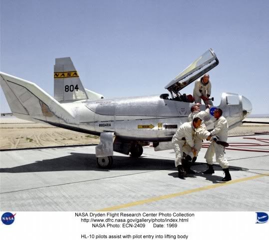
Cockpit of the HL-10 lifting body.
After delivery to NASA in January 1966, the HL-10 made its first flight on December 22, 1966, with research pilot Bruce Peterson in the cockpit. Although the XLR-11 rocket engine (same type used in the Bell X-1) was installed, the first 11 drops from the B-52 launch aircraft were unpowered glide flights to assess handling qualities, stability, and control. In the end, the HL-10 was judged to be the best handling of the three original heavy-weight lifting bodies (M2-F2/F3, HL-10, X-24A).[1]
The HL-10 was flown 37 times during the lifting body research program and logged the highest altitude and fastest speed in the lifting body program. On February 18, 1970, Air Force test pilot Peter Hoag piloted the HL-10 to Mach 1.86 (1,228 mph). Nine days later, NASA pilot Bill Dana flew the vehicle to 90,030 feet (27,440 m), which became the highest altitude reached in the program.[1]
During a typical lifting body flight, the B-52—with the research vehicle attached to the pylon mount on the right wing between the fuselage and inboard engine pod—flew to a height of about 45,000 feet (14,000 m) and a launch speed of about 450 mph (720 km/h).[1]
Moments after being dropped, the XLR-11 was lit by the pilot. Speed and altitude increased until the engine was shut down by choice or fuel exhaustion, depending upon the individual mission profile. The lifting bodies normally carried enough fuel for about 100 seconds of powered flight and routinely reached from 50,000 feet (15,000 m) to 80,000 feet (24,000 m) and speeds above Mach 1.[1]
Following engine shutdown, the pilot maneuvered the vehicle through a simulated return-from-space corridor into a pre-planned approach for a landing on one of the lakebed runways on Rogers Dry Lake at Edwards. A circular approach was used to lose altitude during the landing phase. On the final approach leg, the pilot increased his rate of descent to build up energy. At about 100 feet (30 m) altitude, a "flare out" maneuver dropped air speed to about 200 mph (320 km/h) for the landing.[1]
Unusual and valuable lessons were learned through the successful flight testing of the HL-10. During the early phases of the Space Shuttle development program, lifting bodies patterned on the HL-10 shape were one of three major types of proposals. These were later rejected as it proved difficult to fit cylindrical fuel tanks into the always-curving fuselage, and from then on most designs focused on more conventional delta wing craft.
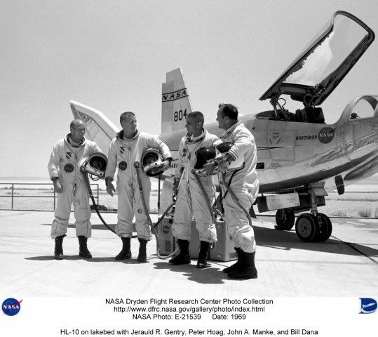
HL-10 pilots John A. Manke - 10 flights
William H. Dana - 9 flights
Jerauld R. Gentry - 9 flights
Peter C. Hoag - 8 flights
Bruce Peterson - 1 flight
Unrealized space flight
According to the book "Wingless Flight", by project engineer R. Dale Reed, if he had had his way, the HL-10 would have flown in space in the early to mid-1970s. Following the cancellation of the Apollo moon project, Reed realized that there would be substantial Apollo hardware left over, including several flight-rated command modules and Saturn V rockets.
His plan was to heavily modify the HL-10 at the Flight Research Center with the addition of an ablative heat shield, reaction controls, and other additional subsystems needed for manned spaceflight. The now space-rated vehicle would have then flown on the Apollo-Saturn V launch vehicle in the same space which originally held the Lunar Module.
Once in Earth orbit, it was planned that a robotic extraction arm would remove the vehicle from the rocket's third stage and place it adjacent to the manned Apollo CSM spacecraft. One of the astronauts, who would be trained to fly the vehicle, would then spacewalk from the Apollo and board the lifting body to perform a pre-reentry check on its systems.
It was planned that there would be two flights in this program. In the first, the lifting body pilot would return to the Apollo and send the HL-10 back to earth unmanned. If this flight was successful, on the next launch, he would then pilot the HL-10 back to earth for a planned landing at Edwards AFB.
Reportedly, Wernher von Braun thought it was a wonderful idea and offered to prepare two Saturn Vs and Apollo Command Service Modules for the mission. Flight Research Center director Paul Bickle said no, stating that this was beyond his expertise or area of interest.[2]
HL-10 flights
Vehicle
Flight #
Date
Pilot
Mach
Velocity /km/h
Altitude /m
Duration
Comments
HL-10 #1
December 22, 1966
Peterson
0.693
735
13,716
00:03:07
First HL-10 Flight
Unpowered glide
HL-10 #2
March 15, 1968
Gentry
0.609
684
13,716
00:04:03
Unpowered glide
HL-10 #3
April 3, 1968
Gentry
0.690
732
13,716
00:04:02
Unpowered glide
HL-10 #4
April 25, 1968
Gentry
0.697
739
13,716
00:04:18
Unpowered glide
HL-10 #5
May 3, 1968
Gentry
0.688
731
13,716
00:04:05
Unpowered glide
HL-10 #6
May 16, 1968
Gentry
0.678
719
13,716
00:04:25
Unpowered glide
HL-10 #7
May 28, 1968
Manke
0.657
698
13,716
00:04:05
Unpowered glide
HL-10 #8
June 11, 1968
Manke
0.635
697
13,716
00:04:06
Unpowered glide
HL-10 #9
June 21, 1968
Gentry
0.637
700
13,716
00:04:31
Unpowered glide
HL-10 #10
September 24, 1968
Gentry
0.682
723
13,716
00:04:05
Unpowered glide
XLR-11 installed
HL-10 #11
October 3, 1968
Manke
0.714
758
13,716
00:04:03
Unpowered glide
HL-10 #12
October 23, 1968
Gentry
0.666
723
12,101
00:03:09
1st powered flight
engine malfunction
landed Rosamond
HL-10 #13
November 13, 1968
Manke
0.840
843
13,000
00:06:25
3 tries to
light engine
HL-10 #14
December 9, 1968
Gentry
0.870
872
14,454
00:06:34
HL-10 #15 April 17, 1969
Manke
0.994
974
16,075
00:06:40
HL-10 #16
April 25, 1969
Dana
0.701
744
13,716
00:04:12
Unpowered glide
HL-10 #17
May 9, 1969
Manke
1.127
1,197
16,246
00:06:50
1st lifting body
supersonic flight
HL-10 #18
May 20, 1969
Dana
0.904
959
14,966
00:06:54
HL-10 #19
May 28, 1969
Manke
1.236
1,312
18,959
00:06:38
HL-10 #20
June 6, 1969
Hoag
0.665
727
13,716
00:03:51
Unpowered glide
HL-10 #21
June 19, 1969
Manke
1.398
1,484
19,538
00:06:18
HL-10 #22
July 23, 1969
Dana
1.444
1,350
19,446
00:06:13
HL-10 #23
August 6, 1969
Manke
1.540
1,656
23,195
00:06:12
1st four
chambered flight
HL-10 #24
September 3, 1969
Dana
1.446
1,542
23,762
00:06:54
HL-10 #25
September 18, 1969
Manke
1.256
1,341
24,137
00:07:06
HL-10 #26
September 30, 1969
Hoag
0.924
980
16,383
00:07:16
HL-10 #27
October 27, 1969
Dana
1.577
1,675
18,474
00:06:57
HL-10 #28
November 3, 1969
Hoag
1.396
1,482
19,544
00:07:19
HL-10 #29
November 17, 1969
Dana
1.594
1,693
19,687
00:06:48
HL-10 #30
November 21, 1969
Hoag
1.432
1,532
24,165
00:06:18
HL-10 #31
December 12, 1969
Dana
1.310
1,402
24,372
00:07:08
HL-10 #32
January 19, 1970
Hoag
1.310
1,399
26,414
00:06:50
HL-10 #33
January 26, 1970
Dana
1.351
1,444
26,726
00:06:51
HL-10 #34
February 18, 1970
Hoag
1.861
1,976
20,516
00:06:20
Fastest lifting
body flight
HL-10 #35
February 27, 1970
Dana
1.314
1,400
27,524
00:06:56
Highest lifting
body flight
HL-10 #36
June 11, 1970
Hoag
0.744
810
13,716
00:03:22
Lift/Drag
powered approach
HL-10 #37
July 17, 1970
Hoag
0.733
803
13,716
00:04:12
Last flight
Aircraft serial number
Northrop HL-10 - NASA 804, 37 flights
Specifications (Northrop HL-10)

NASA HL-10 Lifting Body Diagram
General characteristics
Crew: one pilot
Length: 21 ft 2 in (6.45 m)
Wingspan: 13 ft 7 in (4.15 m)
Height: 9 ft 7 in (2.92 m)
Wing area: 160 ft² (14.9 m²)
Empty: 5,285 lb (2,397 kg)
Loaded: 6,000 lb (2,721 kg)
Maximum takeoff: 10,009 lb (4,540 kg) (propellant wt 3,536 lb - 1,604 kg)
Powerplant: 1 x Reaction Motors XLR-11 four-chamber rocket engine. 8,000 lbf (35.7 kN) thrust
Performance
Maximum speed: 1,228 mph (1,976 km/h)
Range: 45 miles (72 km)
Service ceiling: 90,303 ft (27,524 m)
Rate of climb: ft/min ( m/min)
Wing loading: 62.5 lb/ft² (304.7 kg/m²)
Thrust-to-weight: 1:0.99
Fictional references
In an episode of The Six Million Dollar Man entitled "The Deadly Replay", the HL-10 is identified as the aircraft flown by Col. Steve Austin when he crashed, leading to his transformation into a bionic man, and the HL-10 is also featured in this episode.[3] Other episodes and Martin Caidin's original novel, Cyborg, contradict this, however, by identifying Austin's aircraft as a fictional cousin of the HL-10, the M3-F5.[4] Further confusion is added by the fact that both the HL-10 and the M2-F2 are featured in the opening credits of the TV show.
References
1.^ a b c d e f g "HL-10 Lifting Body fact sheet". Dryden Flight Research Center. NASA. Retrieved 2010-10-04.
2.^ Reed, R. Dale; Darlene Lister (2002). Wingless Flight: The Lifting Body Story. University Press of Kentucky. ISBN 0813190266. also available as a PDF file.
3.^ The Six Million Dollar Man: "The Deadly Replay". Written by Wilton Denmark. First broadcast on Nov. 22, 1974
4.^ Martin Caidin, Cyborg, Arbor House, 1972, and sequel works, plus the 1987 telefilm Return of the Six Million Dollar Man and the Bionic Woman
NASA Dryden HL-10 Photo Collection
Developing and Flight Testing the HL-10 Lifting Body - NASA 1994 (PDF)
A gallery of HL-10 photos, from NASA Dryden:


*******************************************************************
The NASA HL-20
HL-20
HL-20 lifting body
The "luxury" crew rescue vehicle option was the Langley Research Center's $2-billion HL-20 which was loosely based on a Soviet spaceplane design.
Credit: NASA
American manned spaceplane. Study 1988. The HL-20 was a NASA Langley design for a manned spaceplane as a backup to the space shuttle (in case it was abandoned or grounded) and as a CERV (Crew Emergency Return Vehicle) for the Freedom space station.
Also known as the ACRV (Assured Crew Return Vehicle) or PLS (Personnel Launch System). the HL-29 was a lifting body re-entry vehicle based on the Russian BOR-4 design. It was designed for two flight crew, eight passengers, and piloted landing at airfield on landing gear. The HL-20 was studied by contractors and a full size mock-up was built. However the design was not selected for further development. Soyuz was designated as the International Space Station CERV. When doubts about the availability of Soyuz developed in 1995, NASA proceeded with development of the X-38, a NASA Johnson concept - a smaller version of the X-24 lifting body with a parafoil.
During launch a fairing from the Titan IV booster to the spacecraft would have had solid rocket motors (154,000 kgf) for launch abort, with parachutes for a tail-down water landing.
History
In 1983, the Vehicle Analysis Branch began the investigation of the BOR-4 small spaceplane being orbited several times by the Soviets starting in 1982 and recovered in the Indian Ocean and Black Sea. During recovery operations of the space plane in the Indian Ocean, an Australian P-3 Orion aircraft obtained photographs of the vehicle both floating in the water and being hauled aboard the recovery ship. This provided valuable insights into the shape, weight and centre of gravity of the vehicle. Based on this information, small wind tunnels models were produced and tested in the NASA Langley wind tunnels. The results demonstrated the vehicle had good aerodynamic characteristics throughout the speed range from orbital entry interface to low supersonic speeds. Wind tunnel tests showed configuration directional stability at all speeds from subsonic to Mach 20, trimmed to maximum L/D with 10 degree elevon deflections in subsonic range, with no control deflection at Mach 0.6 to 0.9, at 3 degree angle of attack in transonic range, and then again with no deflection from Mach 2.0 to Mach 20. The Soviet design had a 2,040 km cross-range capability and an outstandingly benign thermal profile at peak heating conditions.
Langley Research Center (LaRC) continued to investigate the aerodynamic characteristics of this shape and examined some shape changes to improve the low speed aerodynamics from transonic down to subsonic speeds. LaRC personnel who had worked in the 1960's on lifting bodies, especially the HL-10, were available to conduct these aerodynamic and shape modification tests.
Crew Emergency Rescue Vehicle
As a result of the 1986 Space Shuttle Challenger accident, interest rapidly developed in developing a crew emergency rescue vehicle (CERV) for the proposed US/International space station. If the Shuttle was unavailable for use or station astronauts had to return to Earth in an emergency this would provide continued manned assured access to space. In late 1986, Langley began to study the use of the BOR-4 lifting body shape as a CERV. This involved internal layouts, weight estimations, and centre-of-gravity estimates for a vehicle of large enough scale to accommodate up to 8 space station crew members.
This concept, designated the HL-20, was designed for low operations cost, improved flight safety and conventional runway landings. The proposed Personnel Launch System (PLS), would utilize the HL-20 and an expendable launch system to provide manned access complementing the Space Shuttle. A full-size engineering research model of the HL-20 was constructed by the students and faculty of North Carolina State University and North Carolina A & T University for studying crew seating arrangements, habitability, equipment layout and crew ingress and egress. This engineering research model was 8.84 m long and provided the full-scale external and internal definition of the HL-20 for studies at the Langley Research Center.
The PLS mission was to transport people and small amounts of cargo to and from low-Earth orbit. Although not approved for development, the PLS was designed as a complement to the Space Shuttle and was considered for addition to the manned launch capability of the United States for three main reasons:
•Assured manned access to space. In that era of Space Station Freedom and subsequent missions of the Space Exploration Initiative, it was felt to be imperative that the United States have an alternate means of getting people and valuable small cargo to low-Earth orbit and back should the Space Shuttle be unavailable.
•Enhanced crew safety. Unlike the Space Shuttle, the PLS would not have main propulsion engines or a large payload bay. By removing large payload-carrying requirements from personnel delivery missions, the PLS would be a small, compact vehicle. It was then more feasible to design an abort capability to safely recover the crew during critical phases of the launch and return from orbit.
•Affordable costs. As a small vehicle designed with available technologies, the PLS was forecast to have a low development cost. Subsystem simplification and an aircraft approach to PLS ground and flight operations would also greatly lower the costs of operating PLS.
Candidate Shapes
The two designs considered for PLS differed in their aerodynamic characteristics and mission capabilities. The Johnson Space Center's approach used a ballistic bi-conic design shape (L/D of .75 to 1.0) with a parafoil for a precision landing. The Langley Research Center's HL-20 design was a lifting body that could make a conventional runway landing on return from orbit.
History of Lifting-Body Research
Predating and influencing the design of the Space Shuttle, several lifting body craft including M2-F2, M2-F3, HL-10, X-24A, and X-24B were flown by test pilots during the period 1966-1975. The M2-F2 and the HL-10 were proposed in the 1960s to carry 12 people to a space station following launch on a Saturn IB. In the Soviet Union, the BOR-4 shape was developed and studied by Langley based on recovery photographs. The HL-20 PLS concept evolved from the BOR-4 with modifications based on experience with the early US shapes. The "HL" designation stands for horizontal lander, and "20" reflected Langley's long-term involvement with the lifting body concept, which included the Northrop HL-10.
Advantages of Lifting Bodies
A lifting-body spacecraft, such as the HL-20, would have several advantages over other shapes. With higher lift characteristics during flight through the atmosphere while returning from orbit, the spacecraft could reach more land area, and the number of available landing opportunities to specific sites would be increased. Loads during entry, in terms of g-forces, would be limited to about 1.5 G's. This was important when returning sick, injured, or deconditioned Space Station crew members to Earth. Wheeled runway landings would be possible, permitting simple, precision recovery at many sites around the world, including the Kennedy Space Center launch site.
HL-20 PLS Missions
Delivery of passengers to Space Station Freedom would be the primary mission of a PLS. For the baseline space station mission, the crew size would be eight passengers (a space station crew) and two flight crew members.
A typical PLS mission operation scenario, using an HL-20, would commence at the Kennedy Space Center with the HL-20 being processed horizontally in a vehicle processing facility while an expendable launch vehicle was processed vertically in a separate facility. The launch vehicle and HL-20 would be mated at the launch pad and the launch sequence initiated as the space station passed over the launch site.
Following launch, the HL-20 would initially enter a low 185 km orbit to chase after the space station and then transfer up to the space station orbit altitude of 410 km. After rendezvous and docking at Space Station Freedom, crews would be exchanged, followed by a HL-20 return to Earth at the earliest opportunity.
The HL-20 would land horizontally on a runway in manner similar to the Space Shuttle. Total mission duration would not exceed 72 hours.
Other potential missions defined for a PLS included the orbital rescue of stranded astronauts, priority delivery and observation missions, and missions to perform satellite servicing. For these other missions, the basic HL-20 design would be unchanged, but interior subsystems and arrangements would be modified according to crew accommodations, duration, and equipment required for the particular mission.
HL-20 PLS Launch Vehicles
The HL-20 concept of the PLS was adaptable to several launch vehicle concepts. Titan III was an existing booster system which could be used for unmanned prototype launches but would require modification to be used as a manned system. A future launch system option at that time was the National Launch System under study by the Air Force and NASA. Choice of a launch system for the HL-20 PLS would depend both on the required date of initial PLS operations and the cost of booster development and launches.
Design Features
The design philosophy of the HL-20 PLS concept was to complement the Space Shuttle with safe, reliable manned transportation at the lowest cost. Of utmost importance was crew safety with emphasis being given in the HL-20 design to launch abort situations and the protection of the crew during vehicle recovery. Other requirements focused on minimizing life-cycle costs of the system by insuring simple operations, low-cost manufacturing, and high utilization potential.
With an overall length of 8.84 m and span across the wing tips of 7.16 m, the HL-20 PLS concept would be a much smaller craft than the Space Shuttle Orbiter. In fact, the HL-20 could fit within the payload bay of the Shuttle with wings folded. Overall, the HL-20 would weigh 10,000 kg without crew compared to the Space Shuttle Orbiter's empty weight of 84,000 kg. The space available inside for the crew and passengers, although less than the Shuttle, would be more than found in today's small corporate business jets.
A very important aspect of the HL-20 PLS concept which would help insure low cost operations was its design for maintainability. Large exterior access panels permitted technicians easy access to subsystems which would be exposed and easily replaced if required. The vehicle would be processed in a horizontal position. Selection and design of subsystems would emphasize simplicity and reduce maintenance requirements. For example, hydraulic systems would be replaced by all-electric controls. Unlike the Space Shuttle, the HL-20 would not have a payload bay or main engine propulsion, thereby reducing the processing time. The thermal protection system would be similar to the Space Shuttle's, but the much smaller size of the HL-20 would result in major reductions in inspection and maintenance times. These design changes and subsystem simplifications, along with the adoption of aircraft maintenance philosophies, could reduce the HL-20 processing man-hours to less than 10 percent of that used for the Space Shuttle Orbiter.
The design of the HL-20 PLS concept had taken into account crew safety and survivability for various abort modes. The interior layout with a ladder and hatch arrangement was designed to permit rapid egress of passengers and crew for emergencies on the launch pad. For on-the-pad emergencies or during launch where time was a critical element (launch vehicle fire or explosion), the HL-20 would be equipped with emergency escape rockets that would rapidly thrust the PLS away from the booster. The method was similar to that used during the Apollo program. Once at a safe distance, a cluster of three emergency parachutes would open to lower the vehicle to a safe ocean landing. Inflatable flotation devices ensured that it rode high in the water, with at least one of two hatches available for crew emergency egress.
HL-20 Lifting-Body Research
A significant amount of research effort went into experimental and computational investigations of the baseline HL-20 shape. The goal was to amass a data base of information about the system to aid in management decisions for PLS development.
Using the extensive wind tunnel resources at Langley, researchers compiled a comprehensive aerodynamic and aerothermodynamic data base on the HL-20 concept spanning the entire speed range the PLS would fly through. Several models were built for testing in the various tunnels ranging from a 1.5 m model used for force and moment tests at low speeds to 15 cm models used in hypersonic tests. Results showed the shape possesses good flying qualities in all flight regimes. In addition to measurements of aerodynamic properties, experimental aerothermodynamic heating studies were performed. A new thermographic phosphor technique was used to study the heat transfer characteristics of a HL-20 model in high-speed wind tunnel tests. The model, coated with a phosphor, radiated at varying color intensities as a function of temperature during test when illuminated by ultra-violet light.
Computational fluid dynamics (CFD) codes, which mathematically simulate the flow field in the vicinity of the HL-20, were also used at Langley. These advanced computational grid techniques were used in conjunction with wind tunnel tests to study patterns of flow field phenomena, shock waves, stability and control and heating on the windward and leeward surfaces of the vehicle. Such computational analyses become critical in regimes where wind tunnels cannot duplicate the entry environment. For example, heating in the flight environment on this concept was predicted to be within the limits of Space Shuttle-based high-temperature, reusable surface insulation (HRSI) everywhere except at the nose of the vehicle, where Shuttle-based carbon-carbon thermal protection was required.
Two of the major questions that had to be answered about the lifting-body concept were how to control the HL-20 during the high-heating portion of the re-entry from orbit, and what was the proper guidance scheme for use in the landing phase to enhance its flying qualities. Langley researchers used a six-degree-of-freedom trajectory analysis technique along with mass, inertia and aerodynamic properties of the vehicle to investigate the entry phase of flight.
Results showed that the concept could be controlled through the hypersonic entry using only 14 kg of reaction control thruster fuel in nominal cases, or less than 90 kg of fuel in cases where the vehicle centre of gravity was offset and the upper atmosphere density and wind profiles were off-nominal. The entry analysis also showed the effects of using the vehicle's aerodynamic surfaces in conjunction with thrusters for control purposes.
In addition to computer modeling of vehicle controllability during entry, a flight simulator was set up at Langley to permit pilots to study the final landing phase of flight. Starting at an altitude of 4,600 m, the simulation presented the pilot with a realistic view of the approach to a runway landing. Using a side-stick controller, pilots, including one who had flown the X-15 rocketplane and the lifting bodies, demonstrated this configuration to be controllable and capable of pinpoint landings.
In October 1989, Rockwell International (Space Systems Division) began a year-long contracted effort managed by Langley Research Center to perform an in-depth study of PLS design and operations with the HL-20 concept as a baseline for the study. Using a concurrent engineering approach, Rockwell factored supportable, efficient design and operations measured into a detailed, cost-effective design along with a manufacturing plan and operations assessment. A key finding of this study was the realization that while design and technological factors could reduce costs of a new manned space transportation system, further significant savings were possible only if a new operations philosophy was adopted -- treating PLS in a manner similar to an operational airliner rather than a research and development space vehicle.
In October 1991, the Lockheed Advanced Development Company began a study to determine the feasibility of developing a prototype and operational system. The study objectives were to assess technical attributes, to determine flight qualification requirements, and to develop cost and schedule estimates.
A co-operative agreement between NASA, North Carolina State University and North Carolina A&T University led to the construction of a full-scale model of the HL-20 PLS for further human factors research on the concept. Students at the universities, with requirements furnished by Langley and guidance from university instructors, designed the research model during their spring 1990 semester with construction following during the summer.
The human factors research objectives, using this model, were to assess crew ingress and egress operations, assess crew volume and habitability arrangements, and determine visibility requirements for the crew during critical docking and landing operations.
The testing, using Langley Research Center volunteers as subjects, was completed on the HL-20 model in December 1991. Langley volunteers, wearing non-pressurized flight suits and helmets, were put through a series of tests with the craft placed in both horizontal and vertical modes.
The horizontal study found, for example, that a 10-member crew had adequate volume to quickly and in an orderly manner get in and out of the spacecraft. The available volume and proximity to others was found to be more than reasonably acceptable for a 10-member crew. Recommendations for revision included: more side-head room for the last row of seats to accommodate those taller than 170 cm; a wider aisle; removable seats and more training could improve emergency personnel capabilities and performance; more downward viewing capability for the pilot; structural supported in the windows could reduce viewing; and the cockpit display and seat design must be integrated with window placement.
Testing the HL-20 in a vertical position as oriented for launch posed a new set of factors. Getting in and out of the spacecraft, for example, required climbing through a hatch and up or down a ladder. In the horizontal mode, crew members walked along an aisle leading through the tail, which would be the exit-entry path at a space station or on the ground after a runway landing.
Partial-pressure suits, borrowed from the Johnson Space Center in Houston, were used for part of the study. Participants noticed less head room and restricted movement with the bulkier and heavier suits.
The results of the human factors studies showed where improvements in the baseline HL-20 design were desirable. These improvements would have little impact on overall vehicle shape or aerodynamic performance.
In the end, space station Freedom became the International Space Station. As the initial crew emergency rescue vehicle, the Russian Soyuz spacecraft was selected. However NASA, looking for a higher-capacity alternative and concerned about reliable availability of the Soyuz in the future, did begin development of the X-38 CERV in 1997. The X-38 was however based on the Johnson concept of parachute-assisted landing, and used the pure-USA X-24 lifting body shape....
Characteristics
Crew Size: 10. Orbital Storage: 3.00 days. Habitable Volume: 16.40 m3. Crew: 1,270 kg (2,790 lb).
Gross mass: 10,884 kg (23,995 lb).
Payload: 545 kg (1,201 lb).
Height: 8.93 m (29.29 ft).
Span: 7.16 m (23.49 ft).
--------------------------------------------------------------------------------
--------------------------------------------------------------------------------
Associated Countries •USA
--------------------------------------------------------------------------------
See also •Manned
•Rescue BAIL OUT!
In the early 1960’s, in the hey-day of the X-20 Dynasoar, it seemed that the US military would naturally keep building military aerospacecraft that would just keep going higher and faster. It was also supposed that the pilot would have to be given the equivalent of an ejection seat - some means of bailing out of the spacecraft in case of catastrophic failure or enemy attack. More...
•Space station orbit
•Spaceplane
•US Rocketplanes
--------------------------------------------------------------------------------
Associated Launch Vehicles •Titan American orbital launch vehicle. The Titan launch vehicle family was developed by the United States Air Force to meet its medium lift requirements in the 1960's. The designs finally put into production were derived from the Titan II ICBM. Titan outlived the competing NASA Saturn I launch vehicle and the Space Shuttle for military launches. It was finally replaced by the USAF's EELV boosters, the Atlas V and Delta IV. Although conceived as a low-cost, quick-reaction system, Titan was not successful as a commercial launch vehicle. Air Force requirements growth over the years drove its costs up - the Ariane using similar technology provided lower-cost access to space. More...
--------------------------------------------------------------------------------
Associated Manufacturers and Agencies •NASA American agency overseeing development of rockets and spacecraft. National Aeronautics and Space Administration, USA, USA. More...
•NASA Houston American agency overseeing development of rockets and spacecraft. Houston, Houston, USA. More...
--------------------------------------------------------------------------------
Bibliography •"HL-20", Aviation Week and Space Technology, 1991-07-15, page 52.
•"HL-20 MODEL FOR PERSONNEL LAUNCH SYSTEM RESEARCH", NASA Facts On-Line, NF172
--------------------------------------------------------------------------------
--------------------------------------------------------------------------------
HL-20 Chronology
--------------------------------------------------------------------------------
1983 During the Year - . •NASA Langley begins studies leading to HL-20 - . Nation: USA. Spacecraft: HL-20; BOR-4. The Vehicle Analysis Branch began investigation of the Soviet BOR-4. Small models were tested in NASA wind tunnels and demonstrated that the vehicle had good aerodynamic characteristics throughout the speed range from orbital entry interface to low supersonic speeds. The Soviet design had a 2,040 km cross-range capability and an outstandingly benign thermal profile at peak heating conditions. Therefore Langley adopted it as a baseline for a Crew Emergency Rescue Vehicle to back-up or replace the shuttle after the 1986 Challenger accident.
--------------------------------------------------------------------------------
1989 October - . •Rockwell begins year-long contracted study of HL-20 - . Nation: USA. Spacecraft: HL-20; Space Station Freedom. Rockwell International (Space Systems Division) began a year-long contracted effort managed by Langley Research Center to perform an in-depth study of Personnel Logistics System design and operations with the HL-20 concept as a baseline. The spaceplane would supplement the shuttle in support of the Space Station Freedom.
--------------------------------------------------------------------------------
1991 October - . •Lockheed feasibility studies of HL-20 - . Nation: USA. Spacecraft: HL-20; Space Station Freedom. Lockheed Advanced Development Company began a study to determine the feasibility of developing a prototype and operational system. The study objectives were to assess technical attributes, to determine flight qualification requirements, and to develop cost and schedule estimates.
--------------------------------------------------------------------------------
1991 December - . •HL-20 Mock-up tests completed - . Nation: USA. Spacecraft: HL-20; X-38; X-24A; Space Station Freedom. NASA, North Carolina State University and North Carolina A&T University built a full-scale model of the HL-20 for human factors research on the concept. In the end, space station Freedom became the International Space Station. As the initial crew emergency rescue vehicle, the Russian Soyuz spacecraft was selected. However NASA, looking for a higher-capacity alternative and concerned about reliable availability of the Soyuz in the future, did begin development of the X-38 CERV in 1997. The X-38 was however based on the Johnson concept of parachute-assisted landing, and used the pure-USA X-24 lifting body shape....
--------------------------------------------------------------------------------
HL-20 Images
HL-20 3 view
3 view of the HL-20, also known as ACRV (Assured Crew Return Vehicle) and PLS (Personnel Launch System). NASA 1991 design for backup to space shuttle (in case it was abandoned) and/or as crew return vehicle from space station. Lifting body re-entry vehicle clearly based on Russian Spiral design.
Credit: © Mark Wade
--------------------------------------------------------------------------------
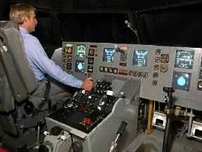
HL-20 Cockpit
Credit: NASA
--------------------------------------------------------------------------------
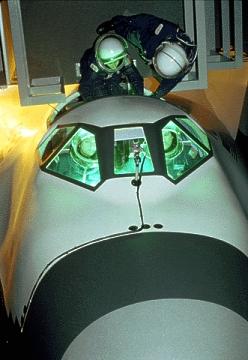
HL-20 Crew EVA
Credit: NASA
--------------------------------------------------------------------------------
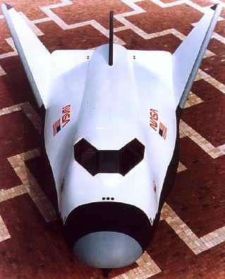
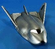
HL-20 Spaceplane
Credit: NASA
--------------------------------------------------------------------------------
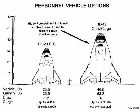
HL-20 / HL-42
HL-20 / HL-42 Comparison
Credit: NASA
--------------------------------------------------------------------------------
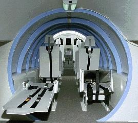
HL-20 Interior
Credit: NASA
--------------------------------------------------------------------------------
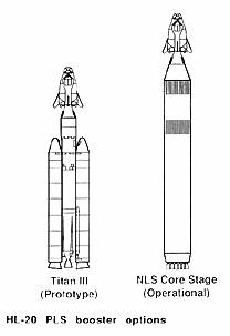
HL-20 Launch Vehicle
HL-20 Launch Vehicle Options
Credit: NASA
--------------------------------------------------------------------------------
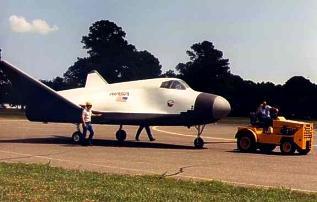
HL-20 Rollout
Credit: NASA
--------------------------------------------------------------------------------
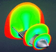
HL-20 / BOR-4
HL-20 / BOR-4 Hypersonic Shockwave
Credit: NASA
--------------------------------------------------------------------------------
And this, from Wikipedia:
HL-20 Personnel Launch System
From Wikipedia, the free encyclopedia
HL-20 Personnel Launch System

HL-20 Mock-Up
Operator: NASA
Mission type: Orbiter
Satellite of: Earth
Mass: 10,884 kg
The HL-20 Personnel Launch System was a circa 1990 NASA spaceplane concept for manned orbital missions studied by NASA's Langley Research Center in Hampton, Virginia. HL-20 was envisaged as a lifting body re-entry vehicle based on the Soviet BOR-4 spaceplane design[1] featuring low operational costs, improved flight safety and a possibility of landing on conventional runways. No flight hardware was ever built.
PLS concept
With increasing national interest in obtaining routine access to space, a number of Earth-to-orbit transportation systems were being studied in the mid-1980s. One, referred to as a Personnel Launch System (PLS), could utilize the HL-20 and an expendable launch system to provide manned access complementing the Space Shuttle. A full-size engineering research model of the HL-20 was constructed in 1990 by the students and faculty of North Carolina State University and North Carolina A & T University for studying crew seating arrangements, habitability, equipment layout and crew ingress and egress. This engineering research model is 29 feet (9 m) long and provided the full-scale external and internal definition of the HL-20 for studies at the Langley Research Center.
The PLS mission is to transport people and small amounts of cargo to and from low-Earth orbit, i.e., a small space taxi system. Although never approved for development, the PLS concept spaceplane was designed as a complement to the Space Shuttle and was being considered an addition to the manned launch capability of the United States for three main reasons:[2]
Assured manned access to space. In the era of Space Station Freedom and subsequent missions of the Space Exploration Initiative, it is imperative that the United States have an alternate means of getting people and valuable small cargo to low-Earth orbit and back should the Space Shuttle be unavailable.
Enhanced crew safety. Unlike the Space Shuttle, the PLS would not have main propulsion engines or large payload bay. By removing large payload-carrying requirements from personnel delivery missions, the PLS would be a small, compact vehicle. It is then more feasible to design an abort capability to safely recover the crew during critical phases of the launch and return from orbit.
Affordable costs. As a small vehicle designed with available technologies, the PLS is forecast to have a low development cost. Subsystem simplification and an aircraft approach to PLS ground and flight operations can also greatly lower the costs of operating PLS.
Two designs being considered[when?] for PLS differ in their aerodynamic characteristics and mission capabilities. While a Johnson Space Center's approach uses a blunt cone shape with a parachute landing system,[clarification needed] the Langley Research Center's design is a lifting body that can make a conventional runway landing on return from orbit.[2]
Lifting body development

Wax model
Predating and influencing the design of the Space Shuttle, several lifting body craft including M2-F2, M2-F3, HL-10, X-24A, and X-24B were flown by test pilots during the period 1966-1975. The M2-F2 and the HL-10 were proposed in the 1960s to carry 12 people to a space station following launch on a Saturn 1B. The HL-20 PLS concept has evolved from these early shapes and based on the Russian versions Kosmos-1445 and Kosmos-1374 and later MiG-105. The "HL" designation stands for horizontal lander, and "20" reflects Langley's long-term involvement with the lifting body concept, which included the Northrup HL-10.
A lifting-body spacecraft, such as the HL-20, would have several advantages over other shapes. With higher lift characteristics during flight through the atmosphere while returning from orbit, the spacecraft can reach more land area, and the number of available landing opportunities to specific sites would be increased. G-forces loads during entry would be limited to about 1.5 G. This is important when returning sick, injured, or deconditioned Space Station crew members to Earth. Wheeled runway landings would be possible, permitting simple, precision recovery at many sites around the world, including the Kennedy Space Center launch site.[2][Full citation needed]
Proposed missions

Return from space station
Originally, delivery of passengers to Space Station Freedom would have been the primary mission of a PLS. For the baseline space station mission, depending on design the crew size would be either eight or ten crew members.[3][Full citation needed]
A typical PLS mission operation scenario, using an HL-20, would commence at the Kennedy Space Center with the HL-20 being processed horizontally in a vehicle processing facility while an expendable launch vehicle is processed vertically in a separate facility. The launch vehicle and HL-20 would be mated at the launch pad and the launch sequence initiated as the space station passes over the launch site.
Following launch, the HL-20 would initially enter a low 100-nautical-mile (200 km) orbit to chase after the space station and then transfer up to the space station orbit altitude of 220 nautical miles (410 km). After rendezvous and docking at Space Station Freedom, crews would be exchanged, followed by an HL-20 return to Earth at the earliest opportunity.
The HL-20 would land horizontally on a runway in manner similar to the Space Shuttle. Total mission duration would not exceed 72 hours.[2]
Other potential missions defined for a PLS included the orbital rescue of stranded astronauts, priority delivery and observation missions, and missions to perform satellite servicing. For these other missions, the basic HL-20 design would be unchanged, but interior subsystems and arrangements would be modified according to crew accommodations, duration, and equipment required for the particular mission.[2]
Design features

The HL-20 concept of the PLS is adaptable to several launch vehicle concepts. Titan III was an existing booster system which could have been used for unmanned prototype launches or would require modification to be used as a manned system. A future launch system option would have been the National Launch System under study by the Air Force and NASA in the 90's. Choice of a launch system for the HL-20 PLS would depend both on the required date of initial PLS operations and the cost of booster development and launches.
The design philosophy of the HL-20 PLS concept was to complement the Space Shuttle with safe, reliable manned transportation at the lowest cost.[2] Crew safety was of utmost importance with emphasis being given in the HL-20 design to launch abort situations and the protection of the crew during vehicle recovery.[2] Other requirements had focused on minimizing life-cycle costs of the system by insuring simple operations, low-cost manufacturing, and high utilization potential.[2] When not including the time of the mission, turnaround time was expected to be 43 days.[3]
With an overall length of about 29 feet (9 m) and span across the wingtips of 23.5 feet (7.2 m),the HL-20 PLS concept would be a much smaller craft than the Space Shuttle Orbiter. In fact, the HL-20 could fit within the payload bay of the Shuttle with wings folded. Overall, the HL-20 would weigh 22,000 pounds (10,000 kg) without crew compared to the Space Shuttle Orbiter's empty weight of 185,000 pounds (84,000 kg). The space available inside for the crew and passengers, although less than the Shuttle, would be more than found in today's small corporate business jets.
A very important aspect of the HL-20 PLS concept which would help insure low cost operations is its design for maintainability. Large exterior access panels permit technicians easy access to subsystems which would be exposed and easily replaced if required. The vehicle would be processed in a horizontal position. Selection and design of subsystems would emphasize simplicity and reduce maintenance requirements. For example, hydraulic systems would be replaced by all-electric controls. Unlike the Space Shuttle, the HL-20 would not have a payload bay or main engine propulsion, thereby reducing the processing time. The thermal protection system would be similar to the Space Shuttle's, but the much smaller size of the HL-20 would result in major reductions in inspection and maintenance times. These design changes and subsystem simplifications, along with the adoption of aircraft maintenance philosophies, could reduce the HL-20 processing manhours to less than 10 percent of those currently used for the Space Shuttle Orbiter.
The design of the HL-20 PLS concept has taken into account crew safety and survivability for various abort modes. The interior layout with a ladder and hatch arrangement has been designed to permit rapid egress of passengers and crew for emergencies on the launch pad. For on-the-pad emergencies or during launch where time is a critical element (launch vehicle fire or explosion), the HL-20 would be equipped with emergency escape rockets which can rapidly thrust the PLS away from the booster. The method is similar to that used during the Apollo program. Once at a safe distance, a cluster of three emergency parachutes would open to lower the vehicle to a safe ocean landing. Inflatable flotation devices ensure that it rides high in the water, with at least one of two hatches available for crew emergency egress.
Contracted efforts

Langley volunteers, wearing flight suits and helmets, were put through a series of tests with the craft placed both vertically and horizontally to simulate launch and landing attitudes

The HL-20 was built at Langley in October 1990 and is a full-scale non-flying mockup
In October 1989, Rockwell International (Space Systems Division) began a year-long contracted effort managed by Langley Research Center to perform an in-depth study of PLS design and operations with the HL-20 concept as a baseline for the study. Using a concurrent engineering approach, Rockwell factored supportable, efficient design and operations measures into defining a detailed, cost-effective design along with a manufacturing plan and operations assessment. A key finding of this study was the realization that while design and technological factors could reduce costs of a new manned space transportation system, further significant savings would be possible only if a new operations philosophy were adopted which treated PLS in a manner similar to an operational airliner rather than a research and development space vehicle.
In October 1991, the Lockheed Advanced Development Company began a study to determine the feasibility of developing a prototype and operational system. The study objectives were to assess technical attributes, to determine flight qualification requirements, and to develop cost and schedule estimates.
A cooperative agreement between NASA, North Carolina State University and North Carolina A&T University led to the construction of a full-scale model of the HL-20 PLS for further human factors research on this concept. Students at the universities, with requirements furnished by Langley and guidance from university instructors, designed the research model during their spring 1990 semester with construction following during the summer. The human factors research objectives, using this model, were to assess crew ingress and egress operations, assess crew volume and habitability arrangements, and determine visibility requirements for the crew during critical docking and landing operations.
The testing, using Langley Research Center volunteers as subjects, was completed on the HL-20 model in December 1991. Langley volunteers, wearing non-pressurized flight suits and helmets, were put through a series of tests with the craft placed in both horizontal and vertical modes.
The horizontal study found, for example, that a 10-member crew has adequate volume to quickly and orderly get in and out of the spacecraft; the available volume and proximity to others was more than reasonably acceptable for a 10-member crew; more side-head room was desirable for the last row of seats to accommodate someone taller than 5 feet 7 inches (1.70 m); a wider aisle, removable seats and more training could improve emergency personnel capabilities and performance; more downward viewing capability for the pilot was desirable. The cockpit display and seat design needed to be integrated with window placement.[2]
Testing the HL-20 in a vertical position as oriented for launch posed a new set of factors. Getting in and out of the spacecraft, for example, required climbing through a hatch and up or down a ladder. In the horizontal mode, crew members walked along an aisle leading through the tail, which would be the exit-entry path at a space station or on the ground after a runway landing.
Partial-pressure suits, borrowed from the Johnson Space Center in Houston, were used for part of the study. Participants noticed less head room and restricted movement with the bulkier and heavier suits.
The results of the human factors studies showed where improvements in the baseline HL-20 design were desirable. The improvements would have little impact on overall vehicle shape or aerodynamic performance.
Legacy
The Dream Chaser spacecraft is based on the HL-20 lifting body design. It was developed by SpaceDev for the 2004 Commercial Orbital Transportation Services competition, and is now being developed by Sierra Nevada Corporation for the Commercial Crew Development program (CCDev).
Orbital Sciences Corporation has also proposed an HL-20 derivative for the second round of CCDev funding, the Prometheus spacecraft.
Both vehicles are proposed to launch unfaired atop a man-rated Atlas V launch vehicle.
See also
NASA X-38
Dream Chaser
Prometheus
References
NASA HL-20 web site
1.^ The New York Times - Businesses Take Flight, With Help From NASA (2011-01-31)
2.^ a b c d e f g h i NASA.gov HL-20 model for Personnel Launch System research
3.^ a b X-15/HL-20 Operations Support Comparison
External links
Wikimedia Commons has media related to: HL-20
NASA.gov HL-20 model for Personnel Launch System research
Astronautix.com's HL-20 web page
Aerodynamic Characteristics of HL-20
X-15/HL-20 Operations Support Comparison
Improving the Subsonic Performance of Proposed Personnel Launch System Concept
Design and Fabricatio of the NASA HL-20 Support Cradle and Interior Mockup
Launch-Pad Abort Capabilities of the HL-20 Lifting Body
Design and Fabrication of the NASA HL-20 Full Scale Research Model
HL-20 / BOR-4
HL-20 / BOR-4 Wind Tunnel Model
Credit: NASA
*******************************************************************
The Lockheed/NASA HL-42
From astronautix.com:
HL-42
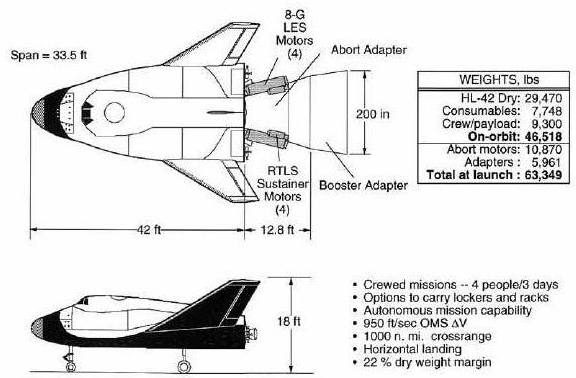
HL-42 Configuration
Credit: NASA
American manned spaceplane. Study 1997. The HL-42 was a reusable, lifting body manned spacecraft designed to be placed into low-Earth orbit by an expendable booster.
Despite extensive study of the concept by NASA Langley in the early 1980's, it was seen as a threat to the shuttle and went no further than the mock-up stage.
The 1997 HL-42 design (HL = horizontal landing) stemmed directly from the HL-20 lifting body vehicle concept studied at Langley Research Center from 1983. It was a 42 percent dimensional scale up of the HL-20, hence the designation HL-42, and also happened to have a body length of 42 feet. It retained key design and operational features of the HL-20 design. The applicable HL-20 design data base included extensive in-house aerodynamic, flight simulation and abort, and human factors research as well as results of contracted studies with Rockwell, Lockheed (Skunk Works), and Boeing in defining efficient manufacturing and operations design and auto-land capabilities.
The HL-42 reference vehicle was a reusable, lifting body spacecraft designed to be placed into low-Earth orbit by an expendable booster. Launch escape motors for use in the event of an abort were attached to the expendable launch vehicle adapter at the base of the HL-42. The spacecraft had a dry mass of 13,365 kg, an on-orbit mass of 21,093 kg, and a launch mass (with booster adapters and launch escape system) of 28,725 kg.
The core of the HL-42 design was an aluminum-lithium, cylindrical, pressurized cabin which contained the crew and/or cargo. It had ingress/egress hatches at the top and rear of the cabin. Docking at the space station occurred at the rear of the HL-42. A 1.27 m space station hatch permitted loading and unloading of cargo as large as space station racks. Extending from the pressurized cabin were frame extensions which supported the lower heat shield structure and defined subsystem bays. A graphite polyimide heat shield structure defined the underside of the HL-42 with the TABI TPS bonded directly to the structure. The upper surface was composed of aluminum lithium removable panels that defined the required aerodynamic shape and allowed access to the subsystems located in the unpressurised bay areas. Shuttle flexible blanket insulation (FRSI) TPS was bonded directly to these panels. The graphite polyimide fins had direct bond TPS (TABI and FRSI) with the addition of advanced carbon-carbon (ACC) for the higher heating leading edges. The vehicle nose cap was also made of ACC.
Flight control consisted of seven moving surfaces -- four body flaps, two elevons on the large fins and an all-moving centre vertical fin. Control movement was effected using electromechanical actuators. Spacecraft power was supplied by Shuttle-derived hydrogen-oxygen fuel cells with limited emergency power backup provided using rechargeable silver-zinc batteries.
The HL-42 did not have a main propulsion system. HL-42 propulsion consisted of a methane (CH4) - liquid oxygen (LOX) orbital maneuvering system (OMS) and reaction control system (RCS) for multi-axis attitude control on orbit and during entry. The CH4-LOX system was selected as a result of the no hypergolic propellant ground rule.
The reference HL-42 was a low-risk technology design. Many subsystems were either direct, off-the-shelf designs or based on existing designs. The only exceptions were in the areas of propulsion (new CH4-LOX systems) and health monitoring avionics. Technologies supporting a 1997 development included aluminum lithium structures, graphite polyimide TPS substructure and fins, and TABI TPS.
Mission Description
Ascent
The HL-42 spacecraft was launched by an expendable booster into a 28 x 405 km injection orbit inclined at 51.6 or 28.5 degrees. The OMS capability was 290 m/s, consistent with maneuvers required to transfer to a 405 km space station orbit, circularize, rendezvous, and de-orbit. Various combinations of crew and cargo (space station racks, early-late access lockers, and EMU suits) up to the 4,300 kg limit could be carried by HL-42 in the pressurized cabin volume
Abort
Crew safety and intact vehicle recovery were two aspects of abort which were addressed by the HL-42 design. The launch escape motors located on the launch vehicle adapter provided a high thrust impulse to rapidly distance the HL-42 from the site of a catastrophic booster failure. While the HL-42 was on the launch pad and during the first 60 seconds of ascent, these abort motors provided for a return-to-launch site (RTLS) capability and an intact runway landing. The booster also provided an additional RTLS capability beyond this initial period. Thereafter, single-engine out transatlantic (TAL) and abort-to-orbit (ATO) options existed throughout the remainder of the ascent powered trajectory. Some booster options had a portion of the ascent where the abort mode resulted in an ocean ditching using emergency parachutes on board the HL-42. Under these conditions the crew was saved, but the vehicle was considered expendable (not refurbished if recovered). Based on the flight rate, this event was estimated to occur only once in the mission model with this vehicle attrition accounted for in the fleet sizing.
Entry
The entry trajectory of the HL-42 was designed not to exceed the temperature capability of the thermal protection system, to not exceed a total acceleration of 1.5 Gs, and to provide a cross-range capability in excess of 1850 km. The entry thermal environment of the HL-42 was similar to that of the HL-20 which had been studied extensively. However, because of its larger dimensions, the heating expected on the nose and fin leading edges was expected to be less severe than on HL-20. The centre-of-gravity of the vehicle with payload in or out was within the flyable range based on the extensive HL-20 aerodynamic data base. The large cross-range capability of HL-42 permitted multiple daily landing opportunities at the launch site, or every orbit landing opportunities if five landing sites were selected from the current list of available Shuttle landing sites.
Servicing Towed Package
To provide for a servicing mission capability, it was assumed one vehicle of the HL-42 fleet would have modifications for an airlock system within the vehicle and inclusion of an RMS servicing arm which telescoped into the base and was housed in the unpressurised service bay area. The servicing mission HL-42 also included a servicing kit which was towed attached to the HL-42. This towed package included:
•Additional OMS/RCS LOX/methane propellants to provide a total orbit maneuver capability to the vehicle of 2980m/s (including reserves).
•1000 kg of hydrazine propellant to refuel the satellite being serviced
•Tanks, pressurization and feed, and propellant transfer systems for the above
•TPS to maintain thermal balance
•A radiator to reject excess heat during the 7-day mission
•A fixed link for satellite hold-down during servicing
•Servicing structure
The servicing kit was housed inside the launch vehicle adapters during launch. During ascent, the adapters split apart exposing the towed package. In a launch abort, the towed package links to HL-42 were severed, and the package was left with the launch vehicle.
Characteristics
Crew Size: 4. RCS total impulse: 56,800 kgf-sec. Spacecraft delta v: 290 m/s (950 ft/sec).
Gross mass: 21,093 kg (46,502 lb).
Unfuelled mass: 19,093 kg (42,092 lb).
Payload: 4,300 kg (9,400 lb).
Height: 12.80 m (41.90 ft).
Span: 10.21 m (33.49 ft).
Specific impulse: 300 s.
--------------------------------------------------------------------------------
--------------------------------------------------------------------------------
Associated Countries •USA
--------------------------------------------------------------------------------
See also •Manned
•Spaceplane
•Suborbital
•US Rocketplanes
--------------------------------------------------------------------------------
Associated Launch Vehicles •Titan American orbital launch vehicle. The Titan launch vehicle family was developed by the United States Air Force to meet its medium lift requirements in the 1960's. The designs finally put into production were derived from the Titan II ICBM. Titan outlived the competing NASA Saturn I launch vehicle and the Space Shuttle for military launches. It was finally replaced by the USAF's EELV boosters, the Atlas V and Delta IV. Although conceived as a low-cost, quick-reaction system, Titan was not successful as a commercial launch vehicle. Air Force requirements growth over the years drove its costs up - the Ariane using similar technology provided lower-cost access to space. More...
--------------------------------------------------------------------------------
Associated Manufacturers and Agencies •NASA American agency overseeing development of rockets and spacecraft. National Aeronautics and Space Administration, USA, USA. More...
•NASA Langley American agency overseeing development of rockets and spacecraft. Langley, USA. More...
--------------------------------------------------------------------------------
Associated Propellants •Lox/CH4
--------------------------------------------------------------------------------
Bibliography •"HL-20 MODEL FOR PERSONNEL LAUNCH SYSTEM RESEARCH", NASA Facts On-Line, NF172
--------------------------------------------------------------------------------
HL-42 Images
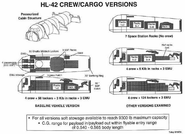
HL-42 Crew/Cargo
HL-42 Crew/Cargo Versions
Credit: NASA
From astronautix.com:
HL-10
HL-10 Lifting Body
HL-10 Lifting Body with B-52 and Test Pilot Dana
Credit: NASA
American manned spaceplane. 37 launches, 1966.12.22 to 1970.07.17 . The HL-10 was the favored lifting body configuration of NASA Langley in the 1960's. It reached Mach 1.86 and 27,700 m during its flight tests.
This configuration was found to be the best of the lifting bodies, and it was used in several of the orbiter proposals in NASA's Phase A and Phase B shuttle design studies. It was also very similar to the winning X-33 configuration proposed by the Lockheed. Purportedly an unmanned test vehicle of this design was tested at orbital speeds by the US Air Force in a black Lockheed Skunk Work's project, possibly on two Titan 3B / Agena D launches in 1972.
The HL-10 was one of five lifting body designs flown at NASA's Dryden Flight Research Center, Edwards, Calif., from July 1966 to November 1975 to study and validate the concept of safely maneuvering and landing a low lift-over-drag vehicle designed for reentry from space. It was now on permanent public display near the main entrance of Dryden.
The other designs were the M2-F2, M2-F3 (rebuilt M2-F2 following a landing accident), X-24A and X-24B (rebuilt X-24A with a different aerodynamic shape).
Wingless lifting bodies attained aerodynamic stability and lift from the shape of the vehicle. Lift resulted from more air pressure on the bottom of the body than on the top. They used energy and aerodynamic lift for in-flight maneuvering and a powerless, glider-like landing.
Background
The original idea of lifting bodies was conceived in 1957 by Dr. Alfred J. Eggers Jr., then the assistant director for Research and Development Analysis and Planning at NASA's Ames Research Center, Moffett Field, Calif.
The lifting body concept was originally tested at Dryden with a plywood prototype designated the M2-F1 and built in late 1962. It featured a plywood shell built by Gus Briegleb, a sailplane builder from Mirage Dry Lake, Calif., placed over a tubular frame built at Dryden. The M2-F1 was towed aloft, first behind an auto and then a C-47 more than 100 times, to validate basic lifting body stability and control characteristics. This led to establishment of the formal program which resulted in the HL-10 and its sister vehicles.
Northrop Corporation built the HL-10. The contract for construction of the HL-10 and the M2-F2, first of the fleet of lifting bodies flown at Dryden and also built by Northrop, was $1.8 million. "HL" stands for horizontal landing, and "10" refers to the tenth design studied by engineers at NASA's Langley Research Center, Hampton, Va.
The HL-10 was delivered to NASA in January 1966. During the next 10 months it was instrumented for the research program and prepared for flight. The HL-10 and the M2-F2 were tested in wind tunnels at Ames Research Center before research flights began.
First flight of the HL-10 was on Dec. 22, 1966, with research pilot Bruce Peterson in the cockpit. Although an XLR-11 rocket engine was installed in the vehicle, the first 11 drop flights from the B-52 launch aircraft were powerless glide flights to assess handling qualities, stability, and control.
The HL-10 was flown 37 times during the lifting body research program and logged the highest altitude and fastest speed in the program. On Feb. 18, 1970, Air Force test pilot Peter Hoag piloted the HL-10 to Mach 1.86 (1,228 mph). Nine days later, NASA pilot Bill Dana flew the vehicle to 90,030 feet, which became the highest altitude reached in the program.
Typical Flight Profile
During a typical lifting body flight, the B-52 -- with the research vehicle attached to the pylon mount on the right wing between the fuselage and inboard engine pod -- flew to a height of about 45,000 feet and a launch speed of about 450 mph.
Moments after being dropped, the XLR-11 rocket engine (same type engine used in the Bell X-l) was ignited by the pilot. Speed and altitude increased until the engine was shut down by choice or fuel exhaustion, depending upon the individual mission profile. The lifting bodies normally carried enough fuel for about 100 seconds of powered flight and routinely reached altitudes of 50,000 to 80,000 feet and speeds above Mach 1.
Following engine shutdown, the pilot maneuvered the vehicle through a simulated return-from-space corridor into a pre-planned approach for a landing on one of the lakebed runways on Rogers Dry Lake at Edwards. A circular approach was used to lose altitude during the landing phase. On the final approach leg, the pilot increased his rate of descent to build up energy. At about 100 feet altitude, a "flare out" maneuver dropped air speed to about 200 mph for the landing.
The HL-10 helped develop energy management and landing techniques used presently with the space shuttle orbiters.
Specifications
Dimensions: Length, 22 ft. 2 in.; Width, 15 ft. 7 in.; Height, 11 ft. 5 in.; Min. Weight, 5,265 lbs.; Max. Weight, 9,000 lbs (with water ballast tanks full).
Controls: Elevons between vertical and center fins for pitch and roll control. Split rudder on center fin for yaw and speed control. All surfaces used in three-axis stabilizer-augmenter system.
Power: One XLR-11 four-chamber rocket engine fueled by ethyl alcohol and liquid oxygen, producing maximum of 6,000 lbs thrust; built by Chemical Reaction Motors, Inc.
Aux. Power: Silver zinc batteries provided electrical power for control system, flight instruments, radios, cockpit heat, and stability augmentation system. To assist in pre-landing flare, four throttleable hydrogen peroxide rockets provided up to 400 lbs of thrust.
Landing Gear: Main gear was modified T-38 system retracted manually, and lowered by nitrogen pressure. Nose gear was modified T-39 nose gear, retracted manually and lowered with nitrogen pressure.
Pilot Ejection System: Modified F-106 system.
Characteristics
Spacecraft delta v: 850 m/s (2,780 ft/sec).
Gross mass: 4,080 kg (8,990 lb).
Unfuelled mass: 2,780 kg (6,120 lb).
Height: 6.77 m (22.21 ft).
Span: 4.60 m (15.00 ft).
Thrust: 26.40 kN (5,935 lbf).
First date: 12/22/1966 .
Last date: 7/17/1970 .
Number: 37 .
--------------------------------------------------------------------------------
--------------------------------------------------------------------------------
Associated Countries •USA
--------------------------------------------------------------------------------
Associated Engines •XLR11 Reaction Motors, Thiokol Lox/Alcohol rocket engine. Out of Production. Launch thrust 26.67 kN. Rocket engine developed for X-1 in 1940s to break the sound barrier and used twenty years later to power experimental lifting bodies. Four combustion chambers. More...
--------------------------------------------------------------------------------
See also •Manned
•Spaceplane
•Suborbital
•US Rocketplanes
--------------------------------------------------------------------------------
Associated Manufacturers and Agencies •Northrop American manufacturer of rockets and spacecraft. Northrop, USA. More...
--------------------------------------------------------------------------------
Associated Propellants •Lox/Alcohol
--------------------------------------------------------------------------------
Bibliography •Gatland, Kenneth, Manned Spacecraft, Macmillan, New York, 1968.
•Miller, Jay,, The X-Planes, Aerofax, Arlington, Texas, 1988.
•Miller, Ron, The Dream Machines, Krieger, Malabar, Florida, 1993.
•Zhelyez x-plane book,
•Houchin II, Roy and Smith, Terry, "X-20 (7 articles)", Quest, 1994, Volume 3, Issue 4, page 4.
•Peebles, Curtis, "The Origins of the US Space Shuttle - 1", Spaceflight, 1979, Volume 21, page 435.
•NASA Dryden Flight Research Center Web Site, Web Address when accessed: http://www.dfrc.nasa.gov/.
•Grimwood, James M., Project Mercury: A Chronology, NASA Special Publication-4001.
•NASA Report, NASA Factsheet FS-010-DFRC HL-10, Web Address when accessed: http://www.dfrc.nasa.gov/Newsroom/FactSheets/PDF/FS-010-DFRC.pdf.
•NASA Report, Full scale wind tunnel investigation of the HL-10 manned lifting body flight vehicle, Web Address when accessed: http://ntrs.nasa.gov/archive/nasa/casi.ntrs.nasa.gov/19710070745_1971070745.pdf.
•NASA Report, Developing and Flight Testing the HL-10 Lifting Body: A Precursor to the Space Shuttle, Web Address when accessed: http://dtrs.dfrc.nasa.gov/archive/00000234/01/RP1332.pdf.
•NASA Report, Developing and flight testing the HL-10 lifting body: A precursor to the Space Shuttle, Web Address when accessed: http://ntrs.nasa.gov/archive/nasa/casi.ntrs.nasa.gov/19940030197_1994030197.pdf.
•NASA Report, Landing characteristics of a dynamic model of the HL-10 manned lifting entry vehicle, Web Address when accessed: http://ntrs.nasa.gov/archive/nasa/casi.ntrs.nasa.gov/19670001463_1967001463.pdf.
--------------------------------------------------------------------------------
--------------------------------------------------------------------------------
HL-10 Chronology
--------------------------------------------------------------------------------
1957 July - August - . •Semiballistic design for a manned reentry spacecraft. - . Nation: USA. Spacecraft: X-24A; HL-10. Summary: Alfred J. Eggers, Jr., of the NACA Ames Aeronautical Laboratory, worked out a semiballistic design for a manned reentry spacecraft..
--------------------------------------------------------------------------------
1962 September - . •M2-F1 lifting body first flight. - . Nation: USA. Spacecraft: M2-F2; HL-10; X-24A. The lifting body concept was first tested at Dryden with a plywood prototype designated the M2-F1 built in late 1962. It featured a plywood shell built by Gus Briegleb, a sailplane builder from Mirage Dry Lake, Calif., placed over a tubular frame built at Dryden. The M2-F1 was towed aloft, first behind an auto and then a C-47 more than 100 times, to validate basic lifting body stability and control characteristics. This led to establishment of the formal program which resulted in the HL-10, M2-F2, M2-F3, X-24A, and X-24B lifting bodies.
--------------------------------------------------------------------------------
1966 January - . •HL-10 delivered to NASA - . Nation: USA. Spacecraft: HL-10. Summary: During the next 10 months it was instrumented for the research program and prepared for flight. The HL-10 and the M2-F2 were tested in wind tunnels at Ames Research Center before research flights began..
--------------------------------------------------------------------------------
1966 December 22 - . •HL-10 Flight 1 - . Crew: Peterson, Bruce. Payload: HL-10 flight 1. Nation: USA. Related Persons: Peterson, Bruce. Program: NASA Lifting Body. Class: Manned. Type: Manned spaceplane. Spacecraft: HL-10. Summary: First flight HL-10. Maximum Speed - 735 kph. Maximum Altitude - 13720 m. Flight Time - 187 sec..
--------------------------------------------------------------------------------
1968 March 15 - . •HL-10 Flight 2 - . Crew: Gentry. Payload: HL-10 flight 2. Nation: USA. Related Persons: Gentry. Program: NASA Lifting Body. Class: Manned. Type: Manned spaceplane. Spacecraft: HL-10. Summary: Maximum Speed - 684 kph. Maximum Altitude - 13720 m. Flight Time - 243 sec..
--------------------------------------------------------------------------------
1968 April 3 - . •HL-10 Flight 3 - . Crew: Gentry. Payload: HL-10 flight 3. Nation: USA. Related Persons: Gentry. Program: NASA Lifting Body. Class: Manned. Type: Manned spaceplane. Spacecraft: HL-10. Summary: Maximum Speed - 732 kph. Maximum Altitude - 13720 m. Flight Time - 242 sec..
--------------------------------------------------------------------------------
1968 April 25 - . •HL-10 Flight 4 - . Crew: Gentry. Payload: HL-10 flight 4. Nation: USA. Related Persons: Gentry. Program: NASA Lifting Body. Class: Manned. Type: Manned spaceplane. Spacecraft: HL-10. Summary: Maximum Speed - 739 kph. Maximum Altitude - 13720 m. Flight Time - 258 sec..
--------------------------------------------------------------------------------
1968 May 3 - . •HL-10 Flight 5 - . Crew: Gentry. Payload: HL-10 flight 5. Nation: USA. Related Persons: Gentry. Program: NASA Lifting Body. Class: Manned. Type: Manned spaceplane. Spacecraft: HL-10. Summary: Maximum Speed - 732 kph. Maximum Altitude - 13720 m. Flight Time - 245 sec..
--------------------------------------------------------------------------------
1968 May 16 - . •HL-10 Flight 6 - . Crew: Gentry. Payload: HL-10 flight 6. Nation: USA. Related Persons: Gentry. Program: NASA Lifting Body. Class: Manned. Type: Manned spaceplane. Spacecraft: HL-10. Summary: Maximum Speed - 719 kph. Maximum Altitude - 13720 m. Flight Time - 265 sec..
--------------------------------------------------------------------------------
1968 May 28 - . •HL-10 Flight 7 - . Crew: Manke. Payload: HL-10 flight 7. Nation: USA. Related Persons: Manke. Program: NASA Lifting Body. Class: Manned. Type: Manned spaceplane. Spacecraft: HL-10. Summary: Maximum Speed - 698 kph. Maximum Altitude - 13720 m. Flight Time - 245 sec..
--------------------------------------------------------------------------------
1968 June 11 - . •HL-10 Flight 8 - . Crew: Manke. Payload: HL-10 flight 8. Nation: USA. Related Persons: Manke. Program: NASA Lifting Body. Class: Manned. Type: Manned spaceplane. Spacecraft: HL-10. Summary: Maximum Speed - 697 kph. Maximum Altitude - 13720 m. Flight Time - 246 sec..
--------------------------------------------------------------------------------
1968 June 21 - . •HL-10 Flight 9 - . Crew: Gentry. Payload: HL-10 flight 9. Nation: USA. Related Persons: Gentry. Program: NASA Lifting Body. Class: Manned. Type: Manned spaceplane. Spacecraft: HL-10. Summary: Maximum Speed - 681 kph. Maximum Altitude - 13720 m. Flight Time - 271 sec..
--------------------------------------------------------------------------------
1968 September 24 - . •HL-10 Flight 10 - . Crew: Gentry. Payload: HL-10 flight 10. Nation: USA. Related Persons: Gentry. Program: NASA Lifting Body. Class: Manned. Type: Manned spaceplane. Spacecraft: HL-10. Summary: XLR-11 engine installed. Maximum Speed - 722 kph. Maximum Altitude - 13720 m. Flight Time - 245 sec..
--------------------------------------------------------------------------------
1968 October 3 - . •HL-10 Flight 11 - . Crew: Manke. Payload: HL-10 flight 11. Nation: USA. Related Persons: Manke. Program: NASA Lifting Body. Class: Manned. Type: Manned spaceplane. Spacecraft: HL-10. Summary: Maximum Speed - 758 kph. Maximum Altitude - 13720 m. Flight Time - 243 sec..
--------------------------------------------------------------------------------
1968 October 23 - . •HL-10 Flight 12 - . Crew: Gentry. Payload: HL-10 flight 12. Nation: USA. Related Persons: Gentry. Program: NASA Lifting Body. Class: Manned. Type: Manned spaceplane. Spacecraft: HL-10. Summary: First powered flight. Premature shutdown. Maximum Speed - 722 kph. Maximum Altitude - 12100 m. Flight Time - 189 sec..
--------------------------------------------------------------------------------
1968 November 13 - . •HL-10 Flight 13 - . Crew: Manke. Payload: HL-10 flight 13. Nation: USA. Related Persons: Manke. Program: NASA Lifting Body. Class: Manned. Type: Manned spaceplane. Spacecraft: HL-10. Summary: 2 chambers, 186-sec powered flight. Maximum Speed - 843 kph. Maximum Altitude - 13000 m. Flight Time - 385 sec..
--------------------------------------------------------------------------------
1968 December 9 - . •HL-10 Flight 14 - . Crew: Gentry. Payload: HL-10 flight 14. Nation: USA. Related Persons: Gentry. Program: NASA Lifting Body. Class: Manned. Type: Manned spaceplane. Spacecraft: HL-10. Summary: 2 chambers. Maximum Speed - 872 kph. Maximum Altitude - 14450 m. Flight Time - 394 sec..
--------------------------------------------------------------------------------
1969 April 17 - . •HL-10 Flight 15 - . Crew: Manke. Payload: HL-10 flight 15. Nation: USA. Related Persons: Manke. Program: NASA Lifting Body. Class: Manned. Type: Manned spaceplane. Spacecraft: HL-10. Summary: 3 chambers. Maximum Speed - 973 kph. Maximum Altitude - 16070 m. Flight Time - 400 sec..
--------------------------------------------------------------------------------
1969 April 25 - . •HL-10 Flight 16 - . Crew: Dana. Payload: HL-10 flight 16. Nation: USA. Related Persons: Dana. Program: NASA Lifting Body. Class: Manned. Type: Manned spaceplane. Spacecraft: HL-10. Summary: Glide. Maximum Speed - 743 kph. Maximum Altitude - 13720 m. Flight Time - 252 sec..
--------------------------------------------------------------------------------
1969 May 9 - . •HL-10 Flight 17 - . Crew: Manke. Payload: HL-10 flight 17. Nation: USA. Related Persons: Manke. Program: NASA Lifting Body. Class: Manned. Type: Manned spaceplane. Spacecraft: HL-10. Summary: 3 chambers, first supersonic. Maximum Speed - 1197 kph. Maximum Altitude - 16250 m. Flight Time - 410 sec..
--------------------------------------------------------------------------------
1969 May 20 - . •HL-10 Flight 18 - . Crew: Dana. Payload: HL-10 flight 18. Nation: USA. Related Persons: Dana. Program: NASA Lifting Body. Class: Manned. Type: Manned spaceplane. Spacecraft: HL-10. Summary: Maximum Speed - 959 kph. Maximum Altitude - 14970 m. Flight Time - 414 sec..
--------------------------------------------------------------------------------
1969 May 28 - . •HL-10 Flight 19 - . Crew: Manke. Payload: HL-10 flight 19. Nation: USA. Related Persons: Manke. Program: NASA Lifting Body. Class: Manned. Type: Manned spaceplane. Spacecraft: HL-10. Summary: 2 chambers. Maximum Speed - 1311 kph. Maximum Altitude - 18960 m. Flight Time - 398 sec..
--------------------------------------------------------------------------------
1969 June 6 - . •HL-10 Flight 20 - . Crew: Hoag. Payload: HL-10 flight 20. Nation: USA. Related Persons: Hoag. Program: NASA Lifting Body. Class: Manned. Type: Manned spaceplane. Spacecraft: HL-10. Summary: Glide. Maximum Speed - 1483 kph. Maximum Altitude - 19540 m. Flight Time - 231 sec..
--------------------------------------------------------------------------------
1969 June 19 - . •HL-10 Flight 21 - . Crew: Manke. Payload: HL-10 flight 21. Nation: USA. Related Persons: Manke. Program: NASA Lifting Body. Class: Manned. Type: Manned spaceplane. Spacecraft: HL-10. Summary: 2 chambers. Maximum Speed - 1483 kph. Maximum Altitude - 19540 m. Flight Time - 378 sec..
--------------------------------------------------------------------------------
1969 June 23 - . •HL-10 Flight 22 - . Crew: Dana. Payload: HL-10 flight 22. Nation: USA. Related Persons: Dana. Program: NASA Lifting Body. Class: Manned. Type: Manned spaceplane. Spacecraft: HL-10. Summary: 2 chambers. Maximum Speed - 1350 kph. Maximum Altitude - 19450 m. Flight Time - 373 sec..
--------------------------------------------------------------------------------
1969 August 6 - . •HL-10 Flight 23 - . Crew: Manke. Payload: HL-10 flight 23. Nation: USA. Related Persons: Manke. Program: NASA Lifting Body. Class: Manned. Type: Manned spaceplane. Spacecraft: HL-10. Summary: First 4-chambered flight. Maximum Speed - 1641 kph. Maximum Altitude - 23190 m. Flight Time - 372 sec..
--------------------------------------------------------------------------------
1969 September 3 - . •HL-10 Flight 24 - . Crew: Dana. Payload: HL-10 flight 24. Nation: USA. Related Persons: Dana. Program: NASA Lifting Body. Class: Manned. Type: Manned spaceplane. Spacecraft: HL-10. Summary: 4 chambers. Maximum Speed - 1541 kph. Maximum Altitude - 23760 m. Flight Time - 414 sec..
--------------------------------------------------------------------------------
1969 September 18 - . •HL-10 Flight 25 - . Crew: Manke. Payload: HL-10 flight 25. Nation: USA. Related Persons: Manke. Program: NASA Lifting Body. Class: Manned. Type: Manned spaceplane. Spacecraft: HL-10. Summary: 4 chambers. Maximum Speed - 1340 kph. Maximum Altitude - 24140 m. Flight Time - 426 sec..
--------------------------------------------------------------------------------
1969 September 30 - . •HL-10 Flight 26 - . Crew: Hoag. Payload: HL-10 flight 26. Nation: USA. Related Persons: Hoag. Program: NASA Lifting Body. Class: Manned. Type: Manned spaceplane. Spacecraft: HL-10. Summary: 2 chambers. Maximum Speed - 780 kph. Maximum Altitude - 16380 m. Flight Time - 436 sec..
--------------------------------------------------------------------------------
1969 October 27 - . •HL-10 Flight 27 - . Crew: Dana. Payload: HL-10 flight 27. Nation: USA. Related Persons: Dana. Program: NASA Lifting Body. Class: Manned. Type: Manned spaceplane. Spacecraft: HL-10. Summary: Maximum Speed - 1675 kph. Maximum Altitude - 18470 m. Flight Time - 417 sec..
--------------------------------------------------------------------------------
1969 November 3 - . •HL-10 Flight 28 - . Crew: Hoag. Payload: HL-10 flight 28. Nation: USA. Related Persons: Hoag. Program: NASA Lifting Body. Class: Manned. Type: Manned spaceplane. Spacecraft: HL-10. Summary: Maximum Speed - 1482kph. Maximum Altitude - 19540 m. Flight Time - 439 sec..
--------------------------------------------------------------------------------
1969 November 17 - . •HL-10 Flight 29 - . Crew: Dana. Payload: HL-10 flight 29. Nation: USA. Related Persons: Dana. Program: NASA Lifting Body. Class: Manned. Type: Manned spaceplane. Spacecraft: HL-10. Summary: Maximum Speed - 1693 kph. Maximum Altitude - 19690 m. Flight Time - 408 sec..
--------------------------------------------------------------------------------
1969 November 21 - . •HL-10 Flight 30 - . Crew: Hoag. Payload: HL-10 flight 30. Nation: USA. Related Persons: Hoag. Program: NASA Lifting Body. Class: Manned. Type: Manned spaceplane. Spacecraft: HL-10. Summary: Maximum Speed - 1532 kph. Maximum Altitude - 24160 m. Flight Time - 378 sec..
--------------------------------------------------------------------------------
1969 December 12 - . •HL-10 Flight 31 - . Crew: Dana. Payload: HL-10 flight 31. Nation: USA. Related Persons: Dana. Program: NASA Lifting Body. Class: Manned. Type: Manned spaceplane. Spacecraft: HL-10. Summary: Maximum Speed - 1401 kph. Maximum Altitude - 24370 m. Flight Time - 428 sec..
--------------------------------------------------------------------------------
1970 January 19 - . •HL-10 Flight 32 - . Crew: Hoag. Payload: HL-10 flight 32. Nation: USA. Related Persons: Hoag. Program: NASA Lifting Body. Class: Manned. Type: Manned spaceplane. Spacecraft: HL-10. Summary: Maximum Speed - 1398 kph. Maximum Altitude - 26410 m. Flight Time - 410 sec..
--------------------------------------------------------------------------------
1970 January 26 - . •HL-10 Flight 33 - . Crew: Dana. Payload: HL-10 flight 33. Nation: USA. Related Persons: Dana. Program: NASA Lifting Body. Class: Manned. Type: Manned spaceplane. Spacecraft: HL-10. Summary: Maximum Speed - 1443 kph. Maximum Altitude - 26730 m. Flight Time - 411 sec..
--------------------------------------------------------------------------------
1970 February 18 - . •HL-10 Flight 34 - . Crew: Hoag. Payload: HL-10 flight 34. Nation: USA. Related Persons: Hoag. Program: NASA Lifting Body. Class: Manned. Type: Manned spaceplane. Spacecraft: HL-10. Summary: Maximum speed. Maximum Speed - 1976 kph. Maximum Altitude - 20520 m. Flight Time - 380 sec..
--------------------------------------------------------------------------------
1970 February 27 - . •HL-10 Flight 35 - . Crew: Dana. Payload: HL-10 flight 35. Nation: USA. Related Persons: Dana. Program: NASA Lifting Body. Class: Manned. Type: Manned spaceplane. Spacecraft: HL-10. Summary: Maximum altitude. Maximum Speed - 1400 kph. Maximum Altitude - 27524 m. Flight Time - 416 sec..
--------------------------------------------------------------------------------
1970 June 11 - . •HL-10 Flight 36 - . Crew: Hoag. Payload: HL-10 flight 36. Nation: USA. Related Persons: Hoag. Program: NASA Lifting Body. Class: Manned. Type: Manned spaceplane. Spacecraft: HL-10. Summary: Glide landing study. Maximum Speed - 809 kph. Maximum Altitude - 13716 m. Flight Time - 202 sec..
--------------------------------------------------------------------------------
1970 July 17 - . •HL-10 Flight 37 - . Crew: Hoag. Payload: HL-10 flight 37. Nation: USA. Related Persons: Hoag. Program: NASA Lifting Body. Class: Manned. Type: Manned spaceplane. Spacecraft: HL-10. Summary: Maximum Speed - 803 kph. Maximum Altitude - 13716 m. Flight Time - 252 sec..
--------------------------------------------------------------------------------
HL-10 Images
HL-10
Three view of the HL-10, the favoured lifting body configuration of NASA's Langley. This configuration was found to be the best of the lifting bodies.
Credit: © Mark Wade
--------------------------------------------------------------------------------
Lifting Bodies
Manned Lifting Bodies
Credit: NASA
--------------------------------------------------------------------------------
HL-10 Lifting Body
Credit: NASA
A gallery of HL-10 photos, from unrealaircraft.com:
And these, from NASA Dryden:
And this, from Wikipedia:
Northrop HL-10
From Wikipedia, the free encyclopedia

HL-10
Role: Lifting body Technology Demonstrator
Manufacturer: Northrop
Designed by: Langley Research Center
First flight: 22 December 1966
Retired: 17 July 1970
Status: On display
Primary user: NASA
Number built: 1
The Northrop HL-10 was one of five heavyweight lifting body designs flown at NASA's Flight Research Center (FRC—later Dryden Flight Research Center), Edwards, California, from July 1966 to November 1975 to study and validate the concept of safely maneuvering and landing a low lift-over-drag vehicle designed for reentry from space.[1] It was a NASA design and was built to evaluate "inverted airfoil" lifting body and delta planform. It currently is on display at the entrance to the Dryden Flight Research Center, Edwards Air Force Base, California.
Development
Northrop Corporation built the HL-10 and Northrop M2-F2, the first two of the fleet of "heavy" lifting bodies flown by the NASA Flight Research Center. The contract for construction of the HL-10 and the M2-F2 was $1.8 million. "HL" stands for horizontal landing, and "10" refers to the tenth design studied by engineers at NASA's Langley Research Center, Hampton, Virginia. Main gear was a modified T-38 system retracted manually,[1] and lowered by nitrogen pressure. Nose gear was modified T-39 unit, retracted manually and lowered with nitrogen pressure. Pilot Ejection System was a modified F-106 system. Silver zinc batteries provided electrical power for control system, flight instruments, radios, cockpit heat, and stability augmentation system. To assist in pre-landing flare, four throttleable hydrogen peroxide rockets provided up to 400 lbf (1.8 kN) of thrust.
Operational history
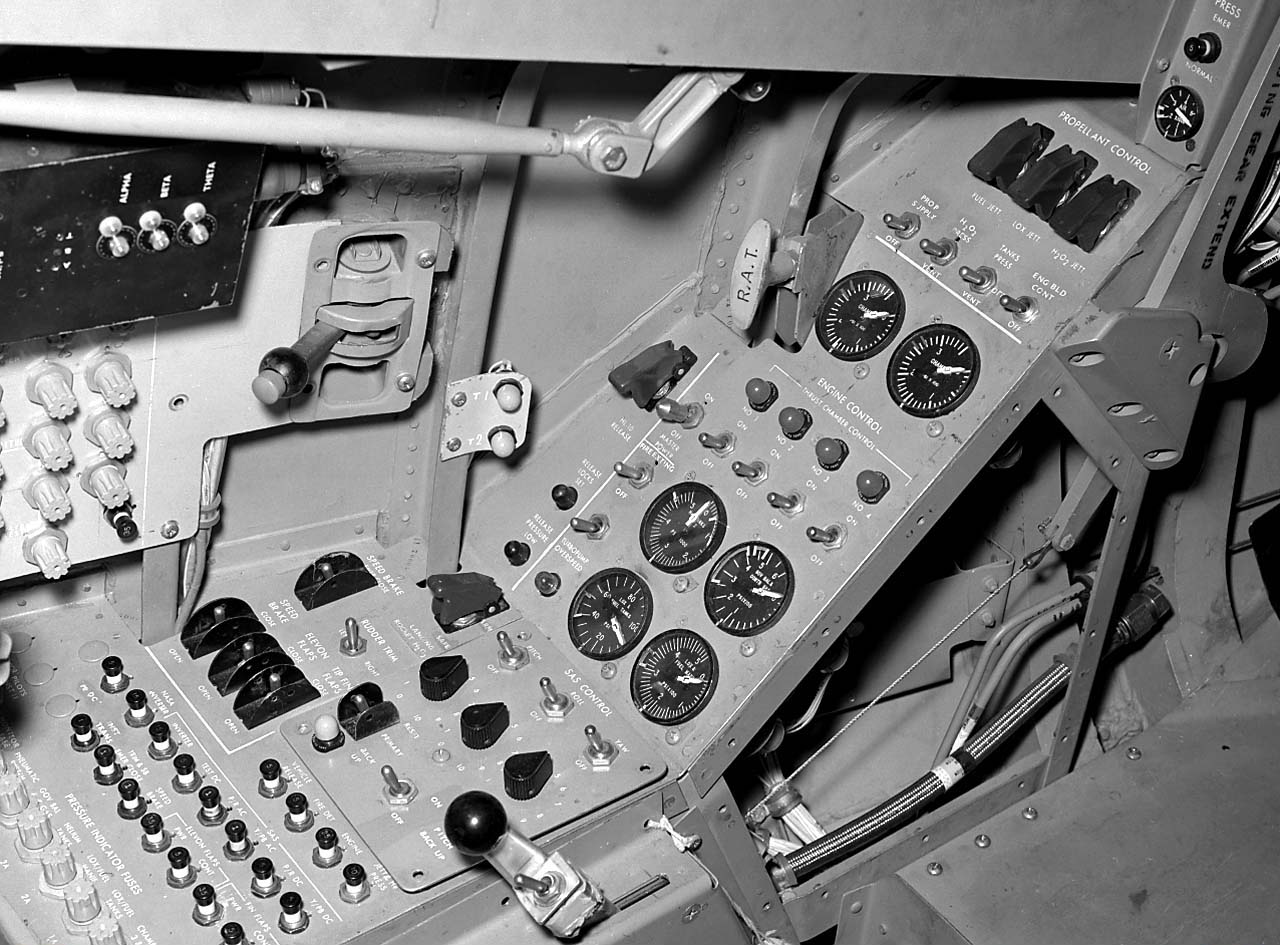
Cockpit of the HL-10 lifting body.
After delivery to NASA in January 1966, the HL-10 made its first flight on December 22, 1966, with research pilot Bruce Peterson in the cockpit. Although the XLR-11 rocket engine (same type used in the Bell X-1) was installed, the first 11 drops from the B-52 launch aircraft were unpowered glide flights to assess handling qualities, stability, and control. In the end, the HL-10 was judged to be the best handling of the three original heavy-weight lifting bodies (M2-F2/F3, HL-10, X-24A).[1]
The HL-10 was flown 37 times during the lifting body research program and logged the highest altitude and fastest speed in the lifting body program. On February 18, 1970, Air Force test pilot Peter Hoag piloted the HL-10 to Mach 1.86 (1,228 mph). Nine days later, NASA pilot Bill Dana flew the vehicle to 90,030 feet (27,440 m), which became the highest altitude reached in the program.[1]
During a typical lifting body flight, the B-52—with the research vehicle attached to the pylon mount on the right wing between the fuselage and inboard engine pod—flew to a height of about 45,000 feet (14,000 m) and a launch speed of about 450 mph (720 km/h).[1]
Moments after being dropped, the XLR-11 was lit by the pilot. Speed and altitude increased until the engine was shut down by choice or fuel exhaustion, depending upon the individual mission profile. The lifting bodies normally carried enough fuel for about 100 seconds of powered flight and routinely reached from 50,000 feet (15,000 m) to 80,000 feet (24,000 m) and speeds above Mach 1.[1]
Following engine shutdown, the pilot maneuvered the vehicle through a simulated return-from-space corridor into a pre-planned approach for a landing on one of the lakebed runways on Rogers Dry Lake at Edwards. A circular approach was used to lose altitude during the landing phase. On the final approach leg, the pilot increased his rate of descent to build up energy. At about 100 feet (30 m) altitude, a "flare out" maneuver dropped air speed to about 200 mph (320 km/h) for the landing.[1]
Unusual and valuable lessons were learned through the successful flight testing of the HL-10. During the early phases of the Space Shuttle development program, lifting bodies patterned on the HL-10 shape were one of three major types of proposals. These were later rejected as it proved difficult to fit cylindrical fuel tanks into the always-curving fuselage, and from then on most designs focused on more conventional delta wing craft.
HL-10 pilots John A. Manke - 10 flights
William H. Dana - 9 flights
Jerauld R. Gentry - 9 flights
Peter C. Hoag - 8 flights
Bruce Peterson - 1 flight
Unrealized space flight
According to the book "Wingless Flight", by project engineer R. Dale Reed, if he had had his way, the HL-10 would have flown in space in the early to mid-1970s. Following the cancellation of the Apollo moon project, Reed realized that there would be substantial Apollo hardware left over, including several flight-rated command modules and Saturn V rockets.
His plan was to heavily modify the HL-10 at the Flight Research Center with the addition of an ablative heat shield, reaction controls, and other additional subsystems needed for manned spaceflight. The now space-rated vehicle would have then flown on the Apollo-Saturn V launch vehicle in the same space which originally held the Lunar Module.
Once in Earth orbit, it was planned that a robotic extraction arm would remove the vehicle from the rocket's third stage and place it adjacent to the manned Apollo CSM spacecraft. One of the astronauts, who would be trained to fly the vehicle, would then spacewalk from the Apollo and board the lifting body to perform a pre-reentry check on its systems.
It was planned that there would be two flights in this program. In the first, the lifting body pilot would return to the Apollo and send the HL-10 back to earth unmanned. If this flight was successful, on the next launch, he would then pilot the HL-10 back to earth for a planned landing at Edwards AFB.
Reportedly, Wernher von Braun thought it was a wonderful idea and offered to prepare two Saturn Vs and Apollo Command Service Modules for the mission. Flight Research Center director Paul Bickle said no, stating that this was beyond his expertise or area of interest.[2]
HL-10 flights
Vehicle
Flight #
Date
Pilot
Mach
Velocity /km/h
Altitude /m
Duration
Comments
HL-10 #1
December 22, 1966
Peterson
0.693
735
13,716
00:03:07
First HL-10 Flight
Unpowered glide
HL-10 #2
March 15, 1968
Gentry
0.609
684
13,716
00:04:03
Unpowered glide
HL-10 #3
April 3, 1968
Gentry
0.690
732
13,716
00:04:02
Unpowered glide
HL-10 #4
April 25, 1968
Gentry
0.697
739
13,716
00:04:18
Unpowered glide
HL-10 #5
May 3, 1968
Gentry
0.688
731
13,716
00:04:05
Unpowered glide
HL-10 #6
May 16, 1968
Gentry
0.678
719
13,716
00:04:25
Unpowered glide
HL-10 #7
May 28, 1968
Manke
0.657
698
13,716
00:04:05
Unpowered glide
HL-10 #8
June 11, 1968
Manke
0.635
697
13,716
00:04:06
Unpowered glide
HL-10 #9
June 21, 1968
Gentry
0.637
700
13,716
00:04:31
Unpowered glide
HL-10 #10
September 24, 1968
Gentry
0.682
723
13,716
00:04:05
Unpowered glide
XLR-11 installed
HL-10 #11
October 3, 1968
Manke
0.714
758
13,716
00:04:03
Unpowered glide
HL-10 #12
October 23, 1968
Gentry
0.666
723
12,101
00:03:09
1st powered flight
engine malfunction
landed Rosamond
HL-10 #13
November 13, 1968
Manke
0.840
843
13,000
00:06:25
3 tries to
light engine
HL-10 #14
December 9, 1968
Gentry
0.870
872
14,454
00:06:34
HL-10 #15 April 17, 1969
Manke
0.994
974
16,075
00:06:40
HL-10 #16
April 25, 1969
Dana
0.701
744
13,716
00:04:12
Unpowered glide
HL-10 #17
May 9, 1969
Manke
1.127
1,197
16,246
00:06:50
1st lifting body
supersonic flight
HL-10 #18
May 20, 1969
Dana
0.904
959
14,966
00:06:54
HL-10 #19
May 28, 1969
Manke
1.236
1,312
18,959
00:06:38
HL-10 #20
June 6, 1969
Hoag
0.665
727
13,716
00:03:51
Unpowered glide
HL-10 #21
June 19, 1969
Manke
1.398
1,484
19,538
00:06:18
HL-10 #22
July 23, 1969
Dana
1.444
1,350
19,446
00:06:13
HL-10 #23
August 6, 1969
Manke
1.540
1,656
23,195
00:06:12
1st four
chambered flight
HL-10 #24
September 3, 1969
Dana
1.446
1,542
23,762
00:06:54
HL-10 #25
September 18, 1969
Manke
1.256
1,341
24,137
00:07:06
HL-10 #26
September 30, 1969
Hoag
0.924
980
16,383
00:07:16
HL-10 #27
October 27, 1969
Dana
1.577
1,675
18,474
00:06:57
HL-10 #28
November 3, 1969
Hoag
1.396
1,482
19,544
00:07:19
HL-10 #29
November 17, 1969
Dana
1.594
1,693
19,687
00:06:48
HL-10 #30
November 21, 1969
Hoag
1.432
1,532
24,165
00:06:18
HL-10 #31
December 12, 1969
Dana
1.310
1,402
24,372
00:07:08
HL-10 #32
January 19, 1970
Hoag
1.310
1,399
26,414
00:06:50
HL-10 #33
January 26, 1970
Dana
1.351
1,444
26,726
00:06:51
HL-10 #34
February 18, 1970
Hoag
1.861
1,976
20,516
00:06:20
Fastest lifting
body flight
HL-10 #35
February 27, 1970
Dana
1.314
1,400
27,524
00:06:56
Highest lifting
body flight
HL-10 #36
June 11, 1970
Hoag
0.744
810
13,716
00:03:22
Lift/Drag
powered approach
HL-10 #37
July 17, 1970
Hoag
0.733
803
13,716
00:04:12
Last flight
Aircraft serial number
Northrop HL-10 - NASA 804, 37 flights
Specifications (Northrop HL-10)

NASA HL-10 Lifting Body Diagram
General characteristics
Crew: one pilot
Length: 21 ft 2 in (6.45 m)
Wingspan: 13 ft 7 in (4.15 m)
Height: 9 ft 7 in (2.92 m)
Wing area: 160 ft² (14.9 m²)
Empty: 5,285 lb (2,397 kg)
Loaded: 6,000 lb (2,721 kg)
Maximum takeoff: 10,009 lb (4,540 kg) (propellant wt 3,536 lb - 1,604 kg)
Powerplant: 1 x Reaction Motors XLR-11 four-chamber rocket engine. 8,000 lbf (35.7 kN) thrust
Performance
Maximum speed: 1,228 mph (1,976 km/h)
Range: 45 miles (72 km)
Service ceiling: 90,303 ft (27,524 m)
Rate of climb: ft/min ( m/min)
Wing loading: 62.5 lb/ft² (304.7 kg/m²)
Thrust-to-weight: 1:0.99
Fictional references
In an episode of The Six Million Dollar Man entitled "The Deadly Replay", the HL-10 is identified as the aircraft flown by Col. Steve Austin when he crashed, leading to his transformation into a bionic man, and the HL-10 is also featured in this episode.[3] Other episodes and Martin Caidin's original novel, Cyborg, contradict this, however, by identifying Austin's aircraft as a fictional cousin of the HL-10, the M3-F5.[4] Further confusion is added by the fact that both the HL-10 and the M2-F2 are featured in the opening credits of the TV show.
References
1.^ a b c d e f g "HL-10 Lifting Body fact sheet". Dryden Flight Research Center. NASA. Retrieved 2010-10-04.
2.^ Reed, R. Dale; Darlene Lister (2002). Wingless Flight: The Lifting Body Story. University Press of Kentucky. ISBN 0813190266. also available as a PDF file.
3.^ The Six Million Dollar Man: "The Deadly Replay". Written by Wilton Denmark. First broadcast on Nov. 22, 1974
4.^ Martin Caidin, Cyborg, Arbor House, 1972, and sequel works, plus the 1987 telefilm Return of the Six Million Dollar Man and the Bionic Woman
NASA Dryden HL-10 Photo Collection
Developing and Flight Testing the HL-10 Lifting Body - NASA 1994 (PDF)
A gallery of HL-10 photos, from NASA Dryden:
*******************************************************************
The NASA HL-20
HL-20
HL-20 lifting body
The "luxury" crew rescue vehicle option was the Langley Research Center's $2-billion HL-20 which was loosely based on a Soviet spaceplane design.
Credit: NASA
American manned spaceplane. Study 1988. The HL-20 was a NASA Langley design for a manned spaceplane as a backup to the space shuttle (in case it was abandoned or grounded) and as a CERV (Crew Emergency Return Vehicle) for the Freedom space station.
Also known as the ACRV (Assured Crew Return Vehicle) or PLS (Personnel Launch System). the HL-29 was a lifting body re-entry vehicle based on the Russian BOR-4 design. It was designed for two flight crew, eight passengers, and piloted landing at airfield on landing gear. The HL-20 was studied by contractors and a full size mock-up was built. However the design was not selected for further development. Soyuz was designated as the International Space Station CERV. When doubts about the availability of Soyuz developed in 1995, NASA proceeded with development of the X-38, a NASA Johnson concept - a smaller version of the X-24 lifting body with a parafoil.
During launch a fairing from the Titan IV booster to the spacecraft would have had solid rocket motors (154,000 kgf) for launch abort, with parachutes for a tail-down water landing.
History
In 1983, the Vehicle Analysis Branch began the investigation of the BOR-4 small spaceplane being orbited several times by the Soviets starting in 1982 and recovered in the Indian Ocean and Black Sea. During recovery operations of the space plane in the Indian Ocean, an Australian P-3 Orion aircraft obtained photographs of the vehicle both floating in the water and being hauled aboard the recovery ship. This provided valuable insights into the shape, weight and centre of gravity of the vehicle. Based on this information, small wind tunnels models were produced and tested in the NASA Langley wind tunnels. The results demonstrated the vehicle had good aerodynamic characteristics throughout the speed range from orbital entry interface to low supersonic speeds. Wind tunnel tests showed configuration directional stability at all speeds from subsonic to Mach 20, trimmed to maximum L/D with 10 degree elevon deflections in subsonic range, with no control deflection at Mach 0.6 to 0.9, at 3 degree angle of attack in transonic range, and then again with no deflection from Mach 2.0 to Mach 20. The Soviet design had a 2,040 km cross-range capability and an outstandingly benign thermal profile at peak heating conditions.
Langley Research Center (LaRC) continued to investigate the aerodynamic characteristics of this shape and examined some shape changes to improve the low speed aerodynamics from transonic down to subsonic speeds. LaRC personnel who had worked in the 1960's on lifting bodies, especially the HL-10, were available to conduct these aerodynamic and shape modification tests.
Crew Emergency Rescue Vehicle
As a result of the 1986 Space Shuttle Challenger accident, interest rapidly developed in developing a crew emergency rescue vehicle (CERV) for the proposed US/International space station. If the Shuttle was unavailable for use or station astronauts had to return to Earth in an emergency this would provide continued manned assured access to space. In late 1986, Langley began to study the use of the BOR-4 lifting body shape as a CERV. This involved internal layouts, weight estimations, and centre-of-gravity estimates for a vehicle of large enough scale to accommodate up to 8 space station crew members.
This concept, designated the HL-20, was designed for low operations cost, improved flight safety and conventional runway landings. The proposed Personnel Launch System (PLS), would utilize the HL-20 and an expendable launch system to provide manned access complementing the Space Shuttle. A full-size engineering research model of the HL-20 was constructed by the students and faculty of North Carolina State University and North Carolina A & T University for studying crew seating arrangements, habitability, equipment layout and crew ingress and egress. This engineering research model was 8.84 m long and provided the full-scale external and internal definition of the HL-20 for studies at the Langley Research Center.
The PLS mission was to transport people and small amounts of cargo to and from low-Earth orbit. Although not approved for development, the PLS was designed as a complement to the Space Shuttle and was considered for addition to the manned launch capability of the United States for three main reasons:
•Assured manned access to space. In that era of Space Station Freedom and subsequent missions of the Space Exploration Initiative, it was felt to be imperative that the United States have an alternate means of getting people and valuable small cargo to low-Earth orbit and back should the Space Shuttle be unavailable.
•Enhanced crew safety. Unlike the Space Shuttle, the PLS would not have main propulsion engines or a large payload bay. By removing large payload-carrying requirements from personnel delivery missions, the PLS would be a small, compact vehicle. It was then more feasible to design an abort capability to safely recover the crew during critical phases of the launch and return from orbit.
•Affordable costs. As a small vehicle designed with available technologies, the PLS was forecast to have a low development cost. Subsystem simplification and an aircraft approach to PLS ground and flight operations would also greatly lower the costs of operating PLS.
Candidate Shapes
The two designs considered for PLS differed in their aerodynamic characteristics and mission capabilities. The Johnson Space Center's approach used a ballistic bi-conic design shape (L/D of .75 to 1.0) with a parafoil for a precision landing. The Langley Research Center's HL-20 design was a lifting body that could make a conventional runway landing on return from orbit.
History of Lifting-Body Research
Predating and influencing the design of the Space Shuttle, several lifting body craft including M2-F2, M2-F3, HL-10, X-24A, and X-24B were flown by test pilots during the period 1966-1975. The M2-F2 and the HL-10 were proposed in the 1960s to carry 12 people to a space station following launch on a Saturn IB. In the Soviet Union, the BOR-4 shape was developed and studied by Langley based on recovery photographs. The HL-20 PLS concept evolved from the BOR-4 with modifications based on experience with the early US shapes. The "HL" designation stands for horizontal lander, and "20" reflected Langley's long-term involvement with the lifting body concept, which included the Northrop HL-10.
Advantages of Lifting Bodies
A lifting-body spacecraft, such as the HL-20, would have several advantages over other shapes. With higher lift characteristics during flight through the atmosphere while returning from orbit, the spacecraft could reach more land area, and the number of available landing opportunities to specific sites would be increased. Loads during entry, in terms of g-forces, would be limited to about 1.5 G's. This was important when returning sick, injured, or deconditioned Space Station crew members to Earth. Wheeled runway landings would be possible, permitting simple, precision recovery at many sites around the world, including the Kennedy Space Center launch site.
HL-20 PLS Missions
Delivery of passengers to Space Station Freedom would be the primary mission of a PLS. For the baseline space station mission, the crew size would be eight passengers (a space station crew) and two flight crew members.
A typical PLS mission operation scenario, using an HL-20, would commence at the Kennedy Space Center with the HL-20 being processed horizontally in a vehicle processing facility while an expendable launch vehicle was processed vertically in a separate facility. The launch vehicle and HL-20 would be mated at the launch pad and the launch sequence initiated as the space station passed over the launch site.
Following launch, the HL-20 would initially enter a low 185 km orbit to chase after the space station and then transfer up to the space station orbit altitude of 410 km. After rendezvous and docking at Space Station Freedom, crews would be exchanged, followed by a HL-20 return to Earth at the earliest opportunity.
The HL-20 would land horizontally on a runway in manner similar to the Space Shuttle. Total mission duration would not exceed 72 hours.
Other potential missions defined for a PLS included the orbital rescue of stranded astronauts, priority delivery and observation missions, and missions to perform satellite servicing. For these other missions, the basic HL-20 design would be unchanged, but interior subsystems and arrangements would be modified according to crew accommodations, duration, and equipment required for the particular mission.
HL-20 PLS Launch Vehicles
The HL-20 concept of the PLS was adaptable to several launch vehicle concepts. Titan III was an existing booster system which could be used for unmanned prototype launches but would require modification to be used as a manned system. A future launch system option at that time was the National Launch System under study by the Air Force and NASA. Choice of a launch system for the HL-20 PLS would depend both on the required date of initial PLS operations and the cost of booster development and launches.
Design Features
The design philosophy of the HL-20 PLS concept was to complement the Space Shuttle with safe, reliable manned transportation at the lowest cost. Of utmost importance was crew safety with emphasis being given in the HL-20 design to launch abort situations and the protection of the crew during vehicle recovery. Other requirements focused on minimizing life-cycle costs of the system by insuring simple operations, low-cost manufacturing, and high utilization potential.
With an overall length of 8.84 m and span across the wing tips of 7.16 m, the HL-20 PLS concept would be a much smaller craft than the Space Shuttle Orbiter. In fact, the HL-20 could fit within the payload bay of the Shuttle with wings folded. Overall, the HL-20 would weigh 10,000 kg without crew compared to the Space Shuttle Orbiter's empty weight of 84,000 kg. The space available inside for the crew and passengers, although less than the Shuttle, would be more than found in today's small corporate business jets.
A very important aspect of the HL-20 PLS concept which would help insure low cost operations was its design for maintainability. Large exterior access panels permitted technicians easy access to subsystems which would be exposed and easily replaced if required. The vehicle would be processed in a horizontal position. Selection and design of subsystems would emphasize simplicity and reduce maintenance requirements. For example, hydraulic systems would be replaced by all-electric controls. Unlike the Space Shuttle, the HL-20 would not have a payload bay or main engine propulsion, thereby reducing the processing time. The thermal protection system would be similar to the Space Shuttle's, but the much smaller size of the HL-20 would result in major reductions in inspection and maintenance times. These design changes and subsystem simplifications, along with the adoption of aircraft maintenance philosophies, could reduce the HL-20 processing man-hours to less than 10 percent of that used for the Space Shuttle Orbiter.
The design of the HL-20 PLS concept had taken into account crew safety and survivability for various abort modes. The interior layout with a ladder and hatch arrangement was designed to permit rapid egress of passengers and crew for emergencies on the launch pad. For on-the-pad emergencies or during launch where time was a critical element (launch vehicle fire or explosion), the HL-20 would be equipped with emergency escape rockets that would rapidly thrust the PLS away from the booster. The method was similar to that used during the Apollo program. Once at a safe distance, a cluster of three emergency parachutes would open to lower the vehicle to a safe ocean landing. Inflatable flotation devices ensured that it rode high in the water, with at least one of two hatches available for crew emergency egress.
HL-20 Lifting-Body Research
A significant amount of research effort went into experimental and computational investigations of the baseline HL-20 shape. The goal was to amass a data base of information about the system to aid in management decisions for PLS development.
Using the extensive wind tunnel resources at Langley, researchers compiled a comprehensive aerodynamic and aerothermodynamic data base on the HL-20 concept spanning the entire speed range the PLS would fly through. Several models were built for testing in the various tunnels ranging from a 1.5 m model used for force and moment tests at low speeds to 15 cm models used in hypersonic tests. Results showed the shape possesses good flying qualities in all flight regimes. In addition to measurements of aerodynamic properties, experimental aerothermodynamic heating studies were performed. A new thermographic phosphor technique was used to study the heat transfer characteristics of a HL-20 model in high-speed wind tunnel tests. The model, coated with a phosphor, radiated at varying color intensities as a function of temperature during test when illuminated by ultra-violet light.
Computational fluid dynamics (CFD) codes, which mathematically simulate the flow field in the vicinity of the HL-20, were also used at Langley. These advanced computational grid techniques were used in conjunction with wind tunnel tests to study patterns of flow field phenomena, shock waves, stability and control and heating on the windward and leeward surfaces of the vehicle. Such computational analyses become critical in regimes where wind tunnels cannot duplicate the entry environment. For example, heating in the flight environment on this concept was predicted to be within the limits of Space Shuttle-based high-temperature, reusable surface insulation (HRSI) everywhere except at the nose of the vehicle, where Shuttle-based carbon-carbon thermal protection was required.
Two of the major questions that had to be answered about the lifting-body concept were how to control the HL-20 during the high-heating portion of the re-entry from orbit, and what was the proper guidance scheme for use in the landing phase to enhance its flying qualities. Langley researchers used a six-degree-of-freedom trajectory analysis technique along with mass, inertia and aerodynamic properties of the vehicle to investigate the entry phase of flight.
Results showed that the concept could be controlled through the hypersonic entry using only 14 kg of reaction control thruster fuel in nominal cases, or less than 90 kg of fuel in cases where the vehicle centre of gravity was offset and the upper atmosphere density and wind profiles were off-nominal. The entry analysis also showed the effects of using the vehicle's aerodynamic surfaces in conjunction with thrusters for control purposes.
In addition to computer modeling of vehicle controllability during entry, a flight simulator was set up at Langley to permit pilots to study the final landing phase of flight. Starting at an altitude of 4,600 m, the simulation presented the pilot with a realistic view of the approach to a runway landing. Using a side-stick controller, pilots, including one who had flown the X-15 rocketplane and the lifting bodies, demonstrated this configuration to be controllable and capable of pinpoint landings.
In October 1989, Rockwell International (Space Systems Division) began a year-long contracted effort managed by Langley Research Center to perform an in-depth study of PLS design and operations with the HL-20 concept as a baseline for the study. Using a concurrent engineering approach, Rockwell factored supportable, efficient design and operations measured into a detailed, cost-effective design along with a manufacturing plan and operations assessment. A key finding of this study was the realization that while design and technological factors could reduce costs of a new manned space transportation system, further significant savings were possible only if a new operations philosophy was adopted -- treating PLS in a manner similar to an operational airliner rather than a research and development space vehicle.
In October 1991, the Lockheed Advanced Development Company began a study to determine the feasibility of developing a prototype and operational system. The study objectives were to assess technical attributes, to determine flight qualification requirements, and to develop cost and schedule estimates.
A co-operative agreement between NASA, North Carolina State University and North Carolina A&T University led to the construction of a full-scale model of the HL-20 PLS for further human factors research on the concept. Students at the universities, with requirements furnished by Langley and guidance from university instructors, designed the research model during their spring 1990 semester with construction following during the summer.
The human factors research objectives, using this model, were to assess crew ingress and egress operations, assess crew volume and habitability arrangements, and determine visibility requirements for the crew during critical docking and landing operations.
The testing, using Langley Research Center volunteers as subjects, was completed on the HL-20 model in December 1991. Langley volunteers, wearing non-pressurized flight suits and helmets, were put through a series of tests with the craft placed in both horizontal and vertical modes.
The horizontal study found, for example, that a 10-member crew had adequate volume to quickly and in an orderly manner get in and out of the spacecraft. The available volume and proximity to others was found to be more than reasonably acceptable for a 10-member crew. Recommendations for revision included: more side-head room for the last row of seats to accommodate those taller than 170 cm; a wider aisle; removable seats and more training could improve emergency personnel capabilities and performance; more downward viewing capability for the pilot; structural supported in the windows could reduce viewing; and the cockpit display and seat design must be integrated with window placement.
Testing the HL-20 in a vertical position as oriented for launch posed a new set of factors. Getting in and out of the spacecraft, for example, required climbing through a hatch and up or down a ladder. In the horizontal mode, crew members walked along an aisle leading through the tail, which would be the exit-entry path at a space station or on the ground after a runway landing.
Partial-pressure suits, borrowed from the Johnson Space Center in Houston, were used for part of the study. Participants noticed less head room and restricted movement with the bulkier and heavier suits.
The results of the human factors studies showed where improvements in the baseline HL-20 design were desirable. These improvements would have little impact on overall vehicle shape or aerodynamic performance.
In the end, space station Freedom became the International Space Station. As the initial crew emergency rescue vehicle, the Russian Soyuz spacecraft was selected. However NASA, looking for a higher-capacity alternative and concerned about reliable availability of the Soyuz in the future, did begin development of the X-38 CERV in 1997. The X-38 was however based on the Johnson concept of parachute-assisted landing, and used the pure-USA X-24 lifting body shape....
Characteristics
Crew Size: 10. Orbital Storage: 3.00 days. Habitable Volume: 16.40 m3. Crew: 1,270 kg (2,790 lb).
Gross mass: 10,884 kg (23,995 lb).
Payload: 545 kg (1,201 lb).
Height: 8.93 m (29.29 ft).
Span: 7.16 m (23.49 ft).
--------------------------------------------------------------------------------
--------------------------------------------------------------------------------
Associated Countries •USA
--------------------------------------------------------------------------------
See also •Manned
•Rescue BAIL OUT!
In the early 1960’s, in the hey-day of the X-20 Dynasoar, it seemed that the US military would naturally keep building military aerospacecraft that would just keep going higher and faster. It was also supposed that the pilot would have to be given the equivalent of an ejection seat - some means of bailing out of the spacecraft in case of catastrophic failure or enemy attack. More...
•Space station orbit
•Spaceplane
•US Rocketplanes
--------------------------------------------------------------------------------
Associated Launch Vehicles •Titan American orbital launch vehicle. The Titan launch vehicle family was developed by the United States Air Force to meet its medium lift requirements in the 1960's. The designs finally put into production were derived from the Titan II ICBM. Titan outlived the competing NASA Saturn I launch vehicle and the Space Shuttle for military launches. It was finally replaced by the USAF's EELV boosters, the Atlas V and Delta IV. Although conceived as a low-cost, quick-reaction system, Titan was not successful as a commercial launch vehicle. Air Force requirements growth over the years drove its costs up - the Ariane using similar technology provided lower-cost access to space. More...
--------------------------------------------------------------------------------
Associated Manufacturers and Agencies •NASA American agency overseeing development of rockets and spacecraft. National Aeronautics and Space Administration, USA, USA. More...
•NASA Houston American agency overseeing development of rockets and spacecraft. Houston, Houston, USA. More...
--------------------------------------------------------------------------------
Bibliography •"HL-20", Aviation Week and Space Technology, 1991-07-15, page 52.
•"HL-20 MODEL FOR PERSONNEL LAUNCH SYSTEM RESEARCH", NASA Facts On-Line, NF172
--------------------------------------------------------------------------------
--------------------------------------------------------------------------------
HL-20 Chronology
--------------------------------------------------------------------------------
1983 During the Year - . •NASA Langley begins studies leading to HL-20 - . Nation: USA. Spacecraft: HL-20; BOR-4. The Vehicle Analysis Branch began investigation of the Soviet BOR-4. Small models were tested in NASA wind tunnels and demonstrated that the vehicle had good aerodynamic characteristics throughout the speed range from orbital entry interface to low supersonic speeds. The Soviet design had a 2,040 km cross-range capability and an outstandingly benign thermal profile at peak heating conditions. Therefore Langley adopted it as a baseline for a Crew Emergency Rescue Vehicle to back-up or replace the shuttle after the 1986 Challenger accident.
--------------------------------------------------------------------------------
1989 October - . •Rockwell begins year-long contracted study of HL-20 - . Nation: USA. Spacecraft: HL-20; Space Station Freedom. Rockwell International (Space Systems Division) began a year-long contracted effort managed by Langley Research Center to perform an in-depth study of Personnel Logistics System design and operations with the HL-20 concept as a baseline. The spaceplane would supplement the shuttle in support of the Space Station Freedom.
--------------------------------------------------------------------------------
1991 October - . •Lockheed feasibility studies of HL-20 - . Nation: USA. Spacecraft: HL-20; Space Station Freedom. Lockheed Advanced Development Company began a study to determine the feasibility of developing a prototype and operational system. The study objectives were to assess technical attributes, to determine flight qualification requirements, and to develop cost and schedule estimates.
--------------------------------------------------------------------------------
1991 December - . •HL-20 Mock-up tests completed - . Nation: USA. Spacecraft: HL-20; X-38; X-24A; Space Station Freedom. NASA, North Carolina State University and North Carolina A&T University built a full-scale model of the HL-20 for human factors research on the concept. In the end, space station Freedom became the International Space Station. As the initial crew emergency rescue vehicle, the Russian Soyuz spacecraft was selected. However NASA, looking for a higher-capacity alternative and concerned about reliable availability of the Soyuz in the future, did begin development of the X-38 CERV in 1997. The X-38 was however based on the Johnson concept of parachute-assisted landing, and used the pure-USA X-24 lifting body shape....
--------------------------------------------------------------------------------
HL-20 Images
HL-20 3 view
3 view of the HL-20, also known as ACRV (Assured Crew Return Vehicle) and PLS (Personnel Launch System). NASA 1991 design for backup to space shuttle (in case it was abandoned) and/or as crew return vehicle from space station. Lifting body re-entry vehicle clearly based on Russian Spiral design.
Credit: © Mark Wade
--------------------------------------------------------------------------------
HL-20 Cockpit
Credit: NASA
--------------------------------------------------------------------------------
HL-20 Crew EVA
Credit: NASA
--------------------------------------------------------------------------------
HL-20 Spaceplane
Credit: NASA
--------------------------------------------------------------------------------
HL-20 / HL-42
HL-20 / HL-42 Comparison
Credit: NASA
--------------------------------------------------------------------------------
HL-20 Interior
Credit: NASA
--------------------------------------------------------------------------------
HL-20 Launch Vehicle
HL-20 Launch Vehicle Options
Credit: NASA
--------------------------------------------------------------------------------
HL-20 Rollout
Credit: NASA
--------------------------------------------------------------------------------
HL-20 / BOR-4
HL-20 / BOR-4 Hypersonic Shockwave
Credit: NASA
--------------------------------------------------------------------------------
And this, from Wikipedia:
HL-20 Personnel Launch System
From Wikipedia, the free encyclopedia
HL-20 Personnel Launch System

HL-20 Mock-Up
Operator: NASA
Mission type: Orbiter
Satellite of: Earth
Mass: 10,884 kg
The HL-20 Personnel Launch System was a circa 1990 NASA spaceplane concept for manned orbital missions studied by NASA's Langley Research Center in Hampton, Virginia. HL-20 was envisaged as a lifting body re-entry vehicle based on the Soviet BOR-4 spaceplane design[1] featuring low operational costs, improved flight safety and a possibility of landing on conventional runways. No flight hardware was ever built.
PLS concept
With increasing national interest in obtaining routine access to space, a number of Earth-to-orbit transportation systems were being studied in the mid-1980s. One, referred to as a Personnel Launch System (PLS), could utilize the HL-20 and an expendable launch system to provide manned access complementing the Space Shuttle. A full-size engineering research model of the HL-20 was constructed in 1990 by the students and faculty of North Carolina State University and North Carolina A & T University for studying crew seating arrangements, habitability, equipment layout and crew ingress and egress. This engineering research model is 29 feet (9 m) long and provided the full-scale external and internal definition of the HL-20 for studies at the Langley Research Center.
The PLS mission is to transport people and small amounts of cargo to and from low-Earth orbit, i.e., a small space taxi system. Although never approved for development, the PLS concept spaceplane was designed as a complement to the Space Shuttle and was being considered an addition to the manned launch capability of the United States for three main reasons:[2]
Assured manned access to space. In the era of Space Station Freedom and subsequent missions of the Space Exploration Initiative, it is imperative that the United States have an alternate means of getting people and valuable small cargo to low-Earth orbit and back should the Space Shuttle be unavailable.
Enhanced crew safety. Unlike the Space Shuttle, the PLS would not have main propulsion engines or large payload bay. By removing large payload-carrying requirements from personnel delivery missions, the PLS would be a small, compact vehicle. It is then more feasible to design an abort capability to safely recover the crew during critical phases of the launch and return from orbit.
Affordable costs. As a small vehicle designed with available technologies, the PLS is forecast to have a low development cost. Subsystem simplification and an aircraft approach to PLS ground and flight operations can also greatly lower the costs of operating PLS.
Two designs being considered[when?] for PLS differ in their aerodynamic characteristics and mission capabilities. While a Johnson Space Center's approach uses a blunt cone shape with a parachute landing system,[clarification needed] the Langley Research Center's design is a lifting body that can make a conventional runway landing on return from orbit.[2]
Lifting body development

Wax model
Predating and influencing the design of the Space Shuttle, several lifting body craft including M2-F2, M2-F3, HL-10, X-24A, and X-24B were flown by test pilots during the period 1966-1975. The M2-F2 and the HL-10 were proposed in the 1960s to carry 12 people to a space station following launch on a Saturn 1B. The HL-20 PLS concept has evolved from these early shapes and based on the Russian versions Kosmos-1445 and Kosmos-1374 and later MiG-105. The "HL" designation stands for horizontal lander, and "20" reflects Langley's long-term involvement with the lifting body concept, which included the Northrup HL-10.
A lifting-body spacecraft, such as the HL-20, would have several advantages over other shapes. With higher lift characteristics during flight through the atmosphere while returning from orbit, the spacecraft can reach more land area, and the number of available landing opportunities to specific sites would be increased. G-forces loads during entry would be limited to about 1.5 G. This is important when returning sick, injured, or deconditioned Space Station crew members to Earth. Wheeled runway landings would be possible, permitting simple, precision recovery at many sites around the world, including the Kennedy Space Center launch site.[2][Full citation needed]
Proposed missions

Return from space station
Originally, delivery of passengers to Space Station Freedom would have been the primary mission of a PLS. For the baseline space station mission, depending on design the crew size would be either eight or ten crew members.[3][Full citation needed]
A typical PLS mission operation scenario, using an HL-20, would commence at the Kennedy Space Center with the HL-20 being processed horizontally in a vehicle processing facility while an expendable launch vehicle is processed vertically in a separate facility. The launch vehicle and HL-20 would be mated at the launch pad and the launch sequence initiated as the space station passes over the launch site.
Following launch, the HL-20 would initially enter a low 100-nautical-mile (200 km) orbit to chase after the space station and then transfer up to the space station orbit altitude of 220 nautical miles (410 km). After rendezvous and docking at Space Station Freedom, crews would be exchanged, followed by an HL-20 return to Earth at the earliest opportunity.
The HL-20 would land horizontally on a runway in manner similar to the Space Shuttle. Total mission duration would not exceed 72 hours.[2]
Other potential missions defined for a PLS included the orbital rescue of stranded astronauts, priority delivery and observation missions, and missions to perform satellite servicing. For these other missions, the basic HL-20 design would be unchanged, but interior subsystems and arrangements would be modified according to crew accommodations, duration, and equipment required for the particular mission.[2]
Design features

The HL-20 concept of the PLS is adaptable to several launch vehicle concepts. Titan III was an existing booster system which could have been used for unmanned prototype launches or would require modification to be used as a manned system. A future launch system option would have been the National Launch System under study by the Air Force and NASA in the 90's. Choice of a launch system for the HL-20 PLS would depend both on the required date of initial PLS operations and the cost of booster development and launches.
The design philosophy of the HL-20 PLS concept was to complement the Space Shuttle with safe, reliable manned transportation at the lowest cost.[2] Crew safety was of utmost importance with emphasis being given in the HL-20 design to launch abort situations and the protection of the crew during vehicle recovery.[2] Other requirements had focused on minimizing life-cycle costs of the system by insuring simple operations, low-cost manufacturing, and high utilization potential.[2] When not including the time of the mission, turnaround time was expected to be 43 days.[3]
With an overall length of about 29 feet (9 m) and span across the wingtips of 23.5 feet (7.2 m),the HL-20 PLS concept would be a much smaller craft than the Space Shuttle Orbiter. In fact, the HL-20 could fit within the payload bay of the Shuttle with wings folded. Overall, the HL-20 would weigh 22,000 pounds (10,000 kg) without crew compared to the Space Shuttle Orbiter's empty weight of 185,000 pounds (84,000 kg). The space available inside for the crew and passengers, although less than the Shuttle, would be more than found in today's small corporate business jets.
A very important aspect of the HL-20 PLS concept which would help insure low cost operations is its design for maintainability. Large exterior access panels permit technicians easy access to subsystems which would be exposed and easily replaced if required. The vehicle would be processed in a horizontal position. Selection and design of subsystems would emphasize simplicity and reduce maintenance requirements. For example, hydraulic systems would be replaced by all-electric controls. Unlike the Space Shuttle, the HL-20 would not have a payload bay or main engine propulsion, thereby reducing the processing time. The thermal protection system would be similar to the Space Shuttle's, but the much smaller size of the HL-20 would result in major reductions in inspection and maintenance times. These design changes and subsystem simplifications, along with the adoption of aircraft maintenance philosophies, could reduce the HL-20 processing manhours to less than 10 percent of those currently used for the Space Shuttle Orbiter.
The design of the HL-20 PLS concept has taken into account crew safety and survivability for various abort modes. The interior layout with a ladder and hatch arrangement has been designed to permit rapid egress of passengers and crew for emergencies on the launch pad. For on-the-pad emergencies or during launch where time is a critical element (launch vehicle fire or explosion), the HL-20 would be equipped with emergency escape rockets which can rapidly thrust the PLS away from the booster. The method is similar to that used during the Apollo program. Once at a safe distance, a cluster of three emergency parachutes would open to lower the vehicle to a safe ocean landing. Inflatable flotation devices ensure that it rides high in the water, with at least one of two hatches available for crew emergency egress.
Contracted efforts

Langley volunteers, wearing flight suits and helmets, were put through a series of tests with the craft placed both vertically and horizontally to simulate launch and landing attitudes

The HL-20 was built at Langley in October 1990 and is a full-scale non-flying mockup
In October 1989, Rockwell International (Space Systems Division) began a year-long contracted effort managed by Langley Research Center to perform an in-depth study of PLS design and operations with the HL-20 concept as a baseline for the study. Using a concurrent engineering approach, Rockwell factored supportable, efficient design and operations measures into defining a detailed, cost-effective design along with a manufacturing plan and operations assessment. A key finding of this study was the realization that while design and technological factors could reduce costs of a new manned space transportation system, further significant savings would be possible only if a new operations philosophy were adopted which treated PLS in a manner similar to an operational airliner rather than a research and development space vehicle.
In October 1991, the Lockheed Advanced Development Company began a study to determine the feasibility of developing a prototype and operational system. The study objectives were to assess technical attributes, to determine flight qualification requirements, and to develop cost and schedule estimates.
A cooperative agreement between NASA, North Carolina State University and North Carolina A&T University led to the construction of a full-scale model of the HL-20 PLS for further human factors research on this concept. Students at the universities, with requirements furnished by Langley and guidance from university instructors, designed the research model during their spring 1990 semester with construction following during the summer. The human factors research objectives, using this model, were to assess crew ingress and egress operations, assess crew volume and habitability arrangements, and determine visibility requirements for the crew during critical docking and landing operations.
The testing, using Langley Research Center volunteers as subjects, was completed on the HL-20 model in December 1991. Langley volunteers, wearing non-pressurized flight suits and helmets, were put through a series of tests with the craft placed in both horizontal and vertical modes.
The horizontal study found, for example, that a 10-member crew has adequate volume to quickly and orderly get in and out of the spacecraft; the available volume and proximity to others was more than reasonably acceptable for a 10-member crew; more side-head room was desirable for the last row of seats to accommodate someone taller than 5 feet 7 inches (1.70 m); a wider aisle, removable seats and more training could improve emergency personnel capabilities and performance; more downward viewing capability for the pilot was desirable. The cockpit display and seat design needed to be integrated with window placement.[2]
Testing the HL-20 in a vertical position as oriented for launch posed a new set of factors. Getting in and out of the spacecraft, for example, required climbing through a hatch and up or down a ladder. In the horizontal mode, crew members walked along an aisle leading through the tail, which would be the exit-entry path at a space station or on the ground after a runway landing.
Partial-pressure suits, borrowed from the Johnson Space Center in Houston, were used for part of the study. Participants noticed less head room and restricted movement with the bulkier and heavier suits.
The results of the human factors studies showed where improvements in the baseline HL-20 design were desirable. The improvements would have little impact on overall vehicle shape or aerodynamic performance.
Legacy
The Dream Chaser spacecraft is based on the HL-20 lifting body design. It was developed by SpaceDev for the 2004 Commercial Orbital Transportation Services competition, and is now being developed by Sierra Nevada Corporation for the Commercial Crew Development program (CCDev).
Orbital Sciences Corporation has also proposed an HL-20 derivative for the second round of CCDev funding, the Prometheus spacecraft.
Both vehicles are proposed to launch unfaired atop a man-rated Atlas V launch vehicle.
See also
NASA X-38
Dream Chaser
Prometheus
References
NASA HL-20 web site
1.^ The New York Times - Businesses Take Flight, With Help From NASA (2011-01-31)
2.^ a b c d e f g h i NASA.gov HL-20 model for Personnel Launch System research
3.^ a b X-15/HL-20 Operations Support Comparison
External links
Wikimedia Commons has media related to: HL-20
NASA.gov HL-20 model for Personnel Launch System research
Astronautix.com's HL-20 web page
Aerodynamic Characteristics of HL-20
X-15/HL-20 Operations Support Comparison
Improving the Subsonic Performance of Proposed Personnel Launch System Concept
Design and Fabricatio of the NASA HL-20 Support Cradle and Interior Mockup
Launch-Pad Abort Capabilities of the HL-20 Lifting Body
Design and Fabrication of the NASA HL-20 Full Scale Research Model
HL-20 / BOR-4
HL-20 / BOR-4 Wind Tunnel Model
Credit: NASA
*******************************************************************
The Lockheed/NASA HL-42
From astronautix.com:
HL-42
HL-42 Configuration
Credit: NASA
American manned spaceplane. Study 1997. The HL-42 was a reusable, lifting body manned spacecraft designed to be placed into low-Earth orbit by an expendable booster.
Despite extensive study of the concept by NASA Langley in the early 1980's, it was seen as a threat to the shuttle and went no further than the mock-up stage.
The 1997 HL-42 design (HL = horizontal landing) stemmed directly from the HL-20 lifting body vehicle concept studied at Langley Research Center from 1983. It was a 42 percent dimensional scale up of the HL-20, hence the designation HL-42, and also happened to have a body length of 42 feet. It retained key design and operational features of the HL-20 design. The applicable HL-20 design data base included extensive in-house aerodynamic, flight simulation and abort, and human factors research as well as results of contracted studies with Rockwell, Lockheed (Skunk Works), and Boeing in defining efficient manufacturing and operations design and auto-land capabilities.
The HL-42 reference vehicle was a reusable, lifting body spacecraft designed to be placed into low-Earth orbit by an expendable booster. Launch escape motors for use in the event of an abort were attached to the expendable launch vehicle adapter at the base of the HL-42. The spacecraft had a dry mass of 13,365 kg, an on-orbit mass of 21,093 kg, and a launch mass (with booster adapters and launch escape system) of 28,725 kg.
The core of the HL-42 design was an aluminum-lithium, cylindrical, pressurized cabin which contained the crew and/or cargo. It had ingress/egress hatches at the top and rear of the cabin. Docking at the space station occurred at the rear of the HL-42. A 1.27 m space station hatch permitted loading and unloading of cargo as large as space station racks. Extending from the pressurized cabin were frame extensions which supported the lower heat shield structure and defined subsystem bays. A graphite polyimide heat shield structure defined the underside of the HL-42 with the TABI TPS bonded directly to the structure. The upper surface was composed of aluminum lithium removable panels that defined the required aerodynamic shape and allowed access to the subsystems located in the unpressurised bay areas. Shuttle flexible blanket insulation (FRSI) TPS was bonded directly to these panels. The graphite polyimide fins had direct bond TPS (TABI and FRSI) with the addition of advanced carbon-carbon (ACC) for the higher heating leading edges. The vehicle nose cap was also made of ACC.
Flight control consisted of seven moving surfaces -- four body flaps, two elevons on the large fins and an all-moving centre vertical fin. Control movement was effected using electromechanical actuators. Spacecraft power was supplied by Shuttle-derived hydrogen-oxygen fuel cells with limited emergency power backup provided using rechargeable silver-zinc batteries.
The HL-42 did not have a main propulsion system. HL-42 propulsion consisted of a methane (CH4) - liquid oxygen (LOX) orbital maneuvering system (OMS) and reaction control system (RCS) for multi-axis attitude control on orbit and during entry. The CH4-LOX system was selected as a result of the no hypergolic propellant ground rule.
The reference HL-42 was a low-risk technology design. Many subsystems were either direct, off-the-shelf designs or based on existing designs. The only exceptions were in the areas of propulsion (new CH4-LOX systems) and health monitoring avionics. Technologies supporting a 1997 development included aluminum lithium structures, graphite polyimide TPS substructure and fins, and TABI TPS.
Mission Description
Ascent
The HL-42 spacecraft was launched by an expendable booster into a 28 x 405 km injection orbit inclined at 51.6 or 28.5 degrees. The OMS capability was 290 m/s, consistent with maneuvers required to transfer to a 405 km space station orbit, circularize, rendezvous, and de-orbit. Various combinations of crew and cargo (space station racks, early-late access lockers, and EMU suits) up to the 4,300 kg limit could be carried by HL-42 in the pressurized cabin volume
Abort
Crew safety and intact vehicle recovery were two aspects of abort which were addressed by the HL-42 design. The launch escape motors located on the launch vehicle adapter provided a high thrust impulse to rapidly distance the HL-42 from the site of a catastrophic booster failure. While the HL-42 was on the launch pad and during the first 60 seconds of ascent, these abort motors provided for a return-to-launch site (RTLS) capability and an intact runway landing. The booster also provided an additional RTLS capability beyond this initial period. Thereafter, single-engine out transatlantic (TAL) and abort-to-orbit (ATO) options existed throughout the remainder of the ascent powered trajectory. Some booster options had a portion of the ascent where the abort mode resulted in an ocean ditching using emergency parachutes on board the HL-42. Under these conditions the crew was saved, but the vehicle was considered expendable (not refurbished if recovered). Based on the flight rate, this event was estimated to occur only once in the mission model with this vehicle attrition accounted for in the fleet sizing.
Entry
The entry trajectory of the HL-42 was designed not to exceed the temperature capability of the thermal protection system, to not exceed a total acceleration of 1.5 Gs, and to provide a cross-range capability in excess of 1850 km. The entry thermal environment of the HL-42 was similar to that of the HL-20 which had been studied extensively. However, because of its larger dimensions, the heating expected on the nose and fin leading edges was expected to be less severe than on HL-20. The centre-of-gravity of the vehicle with payload in or out was within the flyable range based on the extensive HL-20 aerodynamic data base. The large cross-range capability of HL-42 permitted multiple daily landing opportunities at the launch site, or every orbit landing opportunities if five landing sites were selected from the current list of available Shuttle landing sites.
Servicing Towed Package
To provide for a servicing mission capability, it was assumed one vehicle of the HL-42 fleet would have modifications for an airlock system within the vehicle and inclusion of an RMS servicing arm which telescoped into the base and was housed in the unpressurised service bay area. The servicing mission HL-42 also included a servicing kit which was towed attached to the HL-42. This towed package included:
•Additional OMS/RCS LOX/methane propellants to provide a total orbit maneuver capability to the vehicle of 2980m/s (including reserves).
•1000 kg of hydrazine propellant to refuel the satellite being serviced
•Tanks, pressurization and feed, and propellant transfer systems for the above
•TPS to maintain thermal balance
•A radiator to reject excess heat during the 7-day mission
•A fixed link for satellite hold-down during servicing
•Servicing structure
The servicing kit was housed inside the launch vehicle adapters during launch. During ascent, the adapters split apart exposing the towed package. In a launch abort, the towed package links to HL-42 were severed, and the package was left with the launch vehicle.
Characteristics
Crew Size: 4. RCS total impulse: 56,800 kgf-sec. Spacecraft delta v: 290 m/s (950 ft/sec).
Gross mass: 21,093 kg (46,502 lb).
Unfuelled mass: 19,093 kg (42,092 lb).
Payload: 4,300 kg (9,400 lb).
Height: 12.80 m (41.90 ft).
Span: 10.21 m (33.49 ft).
Specific impulse: 300 s.
--------------------------------------------------------------------------------
--------------------------------------------------------------------------------
Associated Countries •USA
--------------------------------------------------------------------------------
See also •Manned
•Spaceplane
•Suborbital
•US Rocketplanes
--------------------------------------------------------------------------------
Associated Launch Vehicles •Titan American orbital launch vehicle. The Titan launch vehicle family was developed by the United States Air Force to meet its medium lift requirements in the 1960's. The designs finally put into production were derived from the Titan II ICBM. Titan outlived the competing NASA Saturn I launch vehicle and the Space Shuttle for military launches. It was finally replaced by the USAF's EELV boosters, the Atlas V and Delta IV. Although conceived as a low-cost, quick-reaction system, Titan was not successful as a commercial launch vehicle. Air Force requirements growth over the years drove its costs up - the Ariane using similar technology provided lower-cost access to space. More...
--------------------------------------------------------------------------------
Associated Manufacturers and Agencies •NASA American agency overseeing development of rockets and spacecraft. National Aeronautics and Space Administration, USA, USA. More...
•NASA Langley American agency overseeing development of rockets and spacecraft. Langley, USA. More...
--------------------------------------------------------------------------------
Associated Propellants •Lox/CH4
--------------------------------------------------------------------------------
Bibliography •"HL-20 MODEL FOR PERSONNEL LAUNCH SYSTEM RESEARCH", NASA Facts On-Line, NF172
--------------------------------------------------------------------------------
HL-42 Images
HL-42 Crew/Cargo
HL-42 Crew/Cargo Versions
Credit: NASA
No comments:
Post a Comment